Two-tier fluidized bed

A fluidized bed and double-layer technology, applied in hearth furnaces, lighting and heating equipment, drying, etc., can solve the problems of low heat energy utilization rate of fluidized bed, affecting drying efficiency, weak wind effect, etc., and achieve structural Simple, improve fluidization quality, and prolong service life

Inactive Publication Date: 2015-04-01
林国友 +2
View PDF5 Cites 4 Cited by
  • Summary
  • Abstract
  • Description
  • Claims
  • Application Information

AI Technical Summary

Problems solved by technology

[0003] In the double-layer fluidized bed in the prior art, when the hot air enters the fluidized bed through the air inlet, the wind force is relatively strong near the air inlet due to the direct blowing of the hot air, while the position farther away from the air inlet is The wind effect is relatively weak, which leads to uneven heating of the hot air after entering the fluidized bed box, which makes the heat energy utilization rate of the fluidized bed low and affects the drying efficiency

Method used


Image

  • Two-tier fluidized bed
  • Two-tier fluidized bed
  • Two-tier fluidized bed

Examples


Embodiment 1

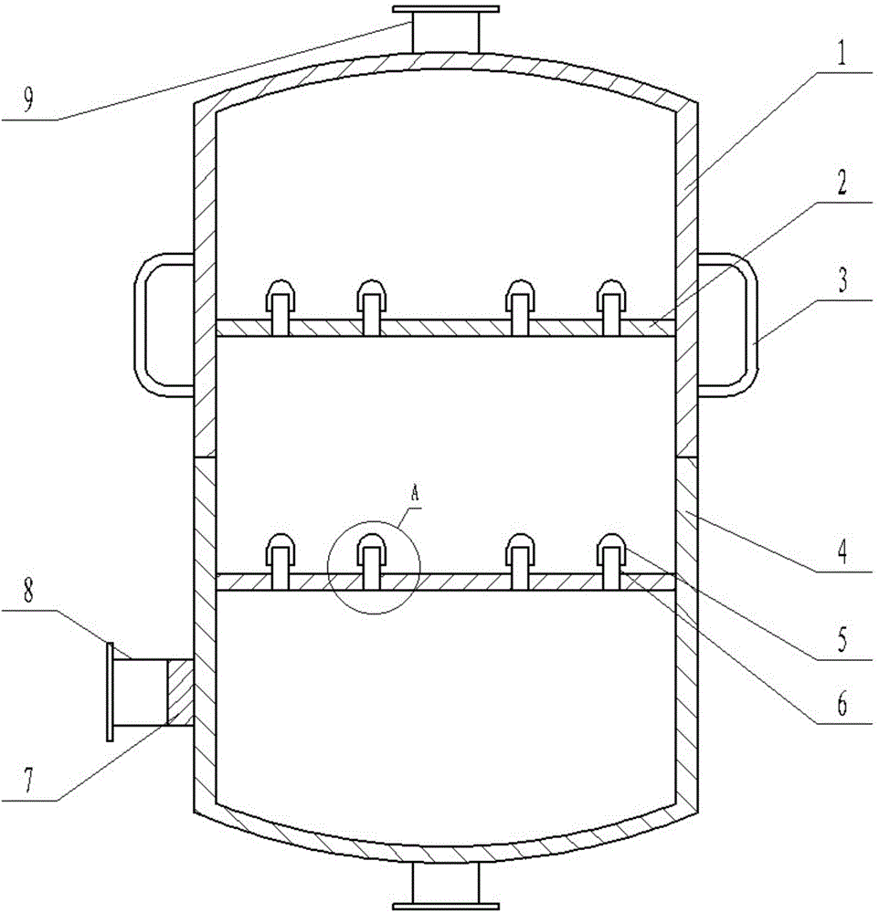
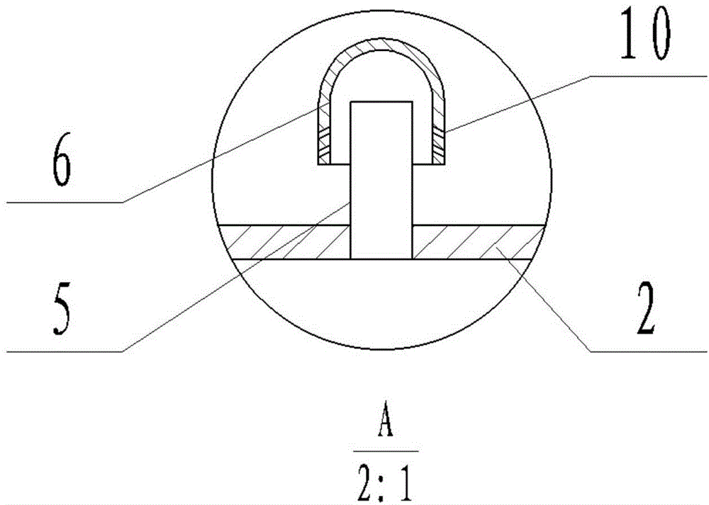
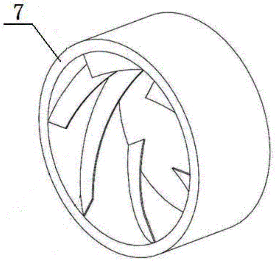
[0026] A double-layer fluidized bed comprises an upper body 1 and a lower body 4, an air inlet 8 and an air outlet 9, and the upper body 1 and the lower body 4 are horizontally provided with a distribution plate 2 for holding materials. The air inlet 8 is arranged on the side wall below the distribution plate 2 of the lower body 4 ; the air outlet 9 is arranged above the upper body 1 . A spiral deflector 7 is provided at the air inlet 8, and the spiral deflector 7 is fan-shaped and inclined, so that the direction of the hot air entering the fluidized bed changes along the direction of the spiral deflector 7, Thereby, the phenomenon of uneven heating caused by direct blowing of hot air is avoided. The distribution plates 2 are provided with ventilation holes, and the ventilation holes are arranged in a staggered manner. A vent pipe 6 is provided on the vent hole on the distribution plate 2; a wind cap 5 is provided on the vent pipe 6. The wind cap 5 is sleeved on the ventilat...

Embodiment 2

[0029] A double-layer fluidized bed comprises an upper body 1 and a lower body 4, an air inlet 8 and an air outlet 9, and the upper body 1 and the lower body 4 are horizontally provided with a distribution plate 2 for holding materials. The air inlet 8 is arranged on the side wall below the distribution plate 2 of the lower body 4 ; the air outlet 9 is arranged above the upper body 1 . The upper body 1 and the lower body 4 can be butted in a sealed manner, and the outer wall of the upper body 1 is provided with a supporting handle 3 for moving, so that the fluidized bed realizes the multifunctionality of the equipment. A spiral deflector 7 is provided at the air inlet 8, and the spiral deflector 7 is fan-shaped and inclined, so that the direction of the hot air entering the fluidized bed changes along the direction of the spiral deflector 7, Thereby, the phenomenon of uneven heating caused by direct blowing of hot air is avoided. The distribution plates 2 are provided with ve...


PUM


Abstract

The invention discloses a two-tier fluidized bed comprising an upper part, a lower part, an air inlet and an air outlet. A distributing plate for holding material is transversely arranged in each of the upper part and the lower part. The air inlet is disposed on the sidewall of the lower part below the distributing plates. The air outlet is disposed above the upper part. A vortex guide plate is disposed at the air inlet. Each distributing plate is provided with air holes which are staggered. The vortex guide plate allows hot air, entering the bed, to be diverted along the vortex guide plate, and thus, the problem of uneven heating caused by direct blow of the hot air is avoided, heat utilization rate of the bed is increased and drying efficiency is good; the bed is simple in structure, convenient to mount, easy to maintain and cost saving.

Description

technical field [0001] The invention belongs to the technical field of chemical equipment, and in particular relates to a double-layer fluidized bed. Background technique [0002] As an efficient reaction setup, fluidized bed is mainly used for gas-solid phase reaction and liquid-solid phase reaction, and has been widely used in chemical, pharmaceutical, environmental protection and other fields. The fluidized bed uses the airflow to act between the critical velocity and the take-out velocity of the particles of the dried material to make the particles form a fluidized motion, thereby enhancing the mass transfer and heat transfer between the two. Production practice shows that the use of a fluidized bed as a reactor has many advantages, such as: strong axial anti-mixing ability; high degree of macro-mixing; when fully mixed and fluent for reaction, the conversion rate can be improved; it can be obtained without additional measures. Uniform temperature distribution, because ...

Claims


Application Information

Patent Timeline
Patent Type & Authority Applications(China)
IPC IPC(8): F26B3/08F26B21/00
Inventor 卢颖林国友覃小红陈程谢美萱黄南概
Owner 林国友
Why Eureka
Try Eureka