
A photocatalytic reactor

A photocatalytic reactor, reactor technology, used in chemical instruments and methods, instruments, scientific instruments, etc.

Active Publication Date: 2016-02-03
FUJIAN NORMAL UNIV
View PDF13 Cites 2 Cited by
  • Summary
  • Abstract
  • Description
  • Claims
  • Application Information

AI Technical Summary

Problems solved by technology

At present, there are many patents on photocatalytic reaction devices (such as ZL201110413781.3 and ZL200910062171.6, etc.), but there are few reports on experimental devices used to accurately control external conditions and study the photocatalytic performance of photocatalytic materials under different conditions.

Method used


Image

  • A photocatalytic reactor
  • A photocatalytic reactor
  • A photocatalytic reactor

Examples


Embodiment Construction

[0050] In order to explain the present invention more clearly, some drawings will be briefly introduced below. Obviously, the accompanying drawings listed below are only some embodiments of the present invention. Other drawings can also be obtained from these drawings under the premise of labor.

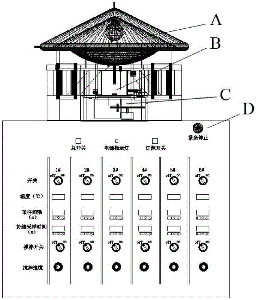
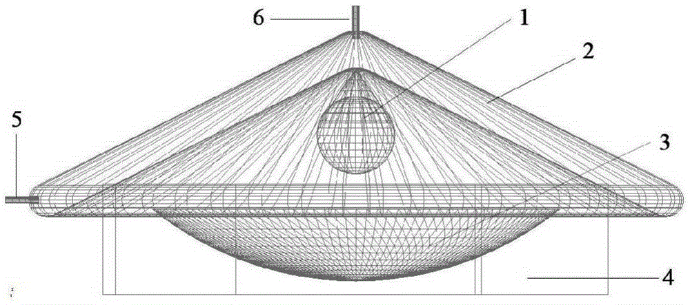
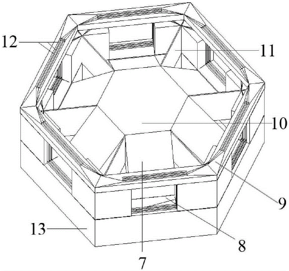
[0051] The following will be combined with Figure 1-Figure 14 , for one of the reactors (the situation of the remaining reactors is exactly the same), the present invention is described in more detail, so that those skilled in the art can refer to and implement.

[0052] as attached figure 1 Shown, the present invention - a kind of photocatalytic reactor, comprises four major parts, as figure 1 Shown are light source system A, reaction system B, sampling system C and control system D respectively.

[0053] Light source system A is mainly used to provide light source, including lamp 1, recessed lampshade 2, light source bottom cover 3, height adjuster 4, lower holder 13, upper hol...


PUM


Abstract

The invention discloses a photocatalytic reactor. The photocatalytic reactor comprises a light source system, a reaction system, a sampling system and a control system and by the photocatalytic reactor, the functions of automatic and simultaneous sampling during the reaction process, synchronous reaction of multiple reactors, the control of reaction conditions and the like can be achieved. The photocatalytic reactor is characterized in that the light source of the light source system can be selected from ultraviolet light, visible light or natural light according to the experimental needs; the light source in the vertical direction produced by the light source system can be reflected by a light splitter and evenly divided into multiple horizontal lights to irradiate different reactors; the reaction system comprises multiple reactors which are same and mutually independent and is used for controlling the temperature of each reactor under the action of an external circulating fluid, each reactor is provided with a sampling switch and thus the manual sampling is achieved or the automatic sampling is achieved in combination with the sampling system. The device is simple in assembly and convenient to operate, the conditions of the photocatalytic reaction can be strictly controlled, the effects of different factors on the photocatalytic reaction are simultaneously explored and the photocatalytic reactor has application prospects in the field of photocatalytic researches.

Description

technical field [0001] The invention relates to the field of performance testing of photocatalytic materials, in particular to an experimental device capable of automatic sampling, control of influencing conditions and simultaneous execution of multiple reaction units. Background technique [0002] The discharge of organic sewage has become a major discharge of industrial sewage. Organic sewage is sewage with organic pollutants as its main components. It is difficult to treat, and it is easy to cause environmental pollution and ecological damage, threatening people's survival and development. At present, sewage treatment methods can be divided into physical methods, chemical methods, biological methods and so on. Although these traditional treatment methods have achieved certain results, there is a risk of secondary pollution and the treatment cost is relatively high. Photocatalytic oxidation is one of the emerging wastewater treatment methods——Advanced Oxidation Processes...

Claims


Application Information

Patent Timeline
Patent Type & Authority Patents(China)
IPC IPC(8): B01J19/12G01N1/10
CPCB01J19/121B01J19/123B01J19/127B01J2219/00761B01J2219/08G01N1/10G01N2001/1031
Inventor 曹长林王坤灿罗永晋陈庆华钱庆荣黄宝铨肖荔人薛珲
Owner FUJIAN NORMAL UNIV
Learn More