Automatic charging machine on punch

An automatic feeding and punching technology, applied to metal processing equipment, feeding devices, manufacturing tools, etc., can solve the problems of increasing feeding time and reducing processing efficiency

Active Publication Date: 2015-04-08
浙江瑞虹机电股份有限公司
View PDF5 Cites 8 Cited by
  • Summary
  • Abstract
  • Description
  • Claims
  • Application Information

AI Technical Summary

Problems solved by technology

But the weak point of existing automatic feeding machine is: the feeding mechanism in the automatic feeding machine is generally a feeding tray, and the manipulator used to take out the raw material steel plate from the feeding tray, when the raw material steel plate in the feeding tray After all the materials are supplied, the equipment must be shut down and the tray must be replaced or artificially filled into the tray, thus increasing the feeding time and reducing the processing efficiency

Method used


Image

  • Automatic charging machine on punch
  • Automatic charging machine on punch
  • Automatic charging machine on punch

Examples


Embodiment Construction

[0015] The preferred embodiments of the present invention will be described in further detail below in conjunction with the accompanying drawings.

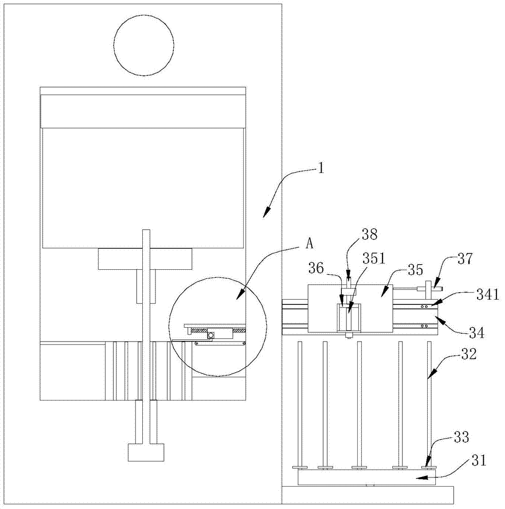
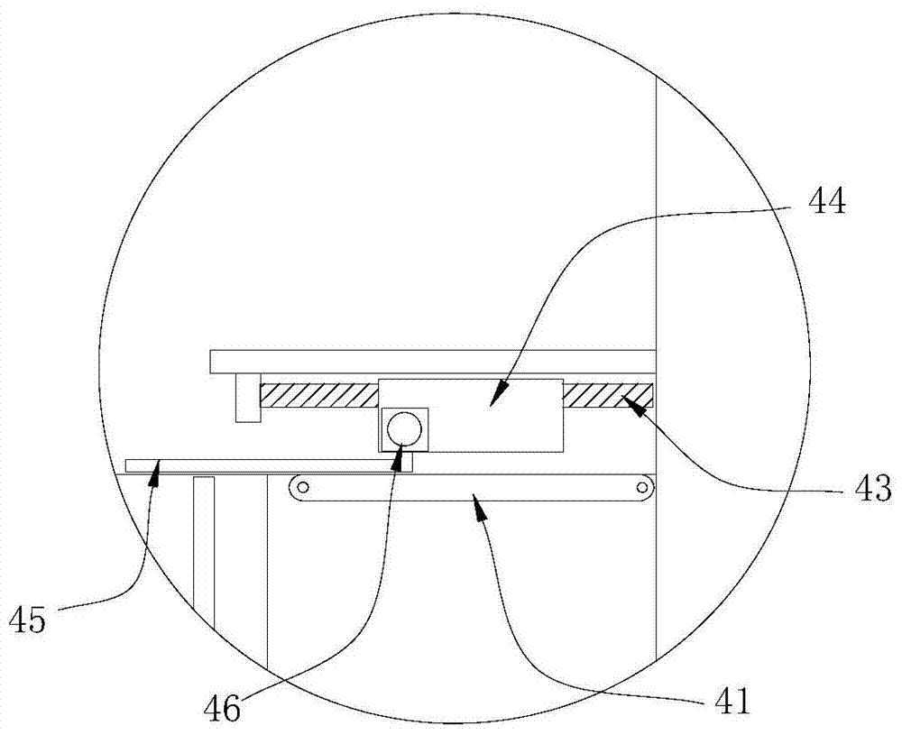
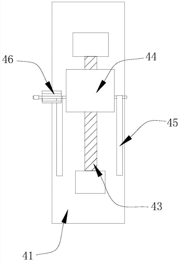
[0016] Such as Figure 1~Figure 4 An automatic feeding machine is shown, and the automatic feeding machine is used in conjunction with a punching machine 1 to make a clutch coil housing for an automobile air conditioner. The feeding machine includes a feeding mechanism for placing raw steel plates, and a feeding mechanism for transporting the raw steel plates to stamping stations. The feeding mechanism includes a conveyor belt 41, a feeding motor, a screw rod 43 and a fixture. The conveyor belt 41 is intermittently driven and transported by a servo motor. The conveying direction of the conveyor belt 41 is towards the stamping station. It is connected with the screw rod 43 in transmission, and the fixture is threadedly engaged with the screw rod 43 . The fixture includes a fixture seat 44, and two fixture arms 45 arranged on the ...


PUM


Abstract

The invention relates to the field of feeding equipment, in particular to an automatic charging machine on a punch. The charging machine comprises a feeding mechanism and a charging mechanism, wherein the charging mechanism comprises a conveying belt for intermittent conveying and a tooling fixture for conveying raw material steel plates on the conveying belt to a punching station; the tooling fixture is movably arranged above the conveying belt; a moving direction of the tooling fixture is parallel to a feeding direction of the conveying belt; the feeding mechanism comprises a feeding frame and a feeding device arranged above the feeding frame; the feeding frame comprises a feeding turntable capable of rotating circumferentially, a plurality of feeding shafts arranged along the periphery of the upper end face of the feeding turntable and feeding check rings capable of moving axially on the feeding shafts; the feeding device comprises a fixing frame located above the feeding frame, a sliding frame arranged on the fixing frame in a transverse sliding manner, and a manipulator for conveying the raw material steel plates on the feeding shaft to the conveying belt; and the manipulator is arranged on the sliding frame in a longitudinal sliding manner. The automatic charging machine can save charging time and improve processing efficiency.

Description

technical field [0001] The invention relates to the field of feeding equipment, in particular to an automatic feeding machine on a punching machine. Background technique [0002] The automobile air conditioner clutch coil housing is formed by stamping a circular raw steel plate. The equipment used includes a punching machine and an automatic feeding machine on it; when in use, the automatic feeding machine transports the raw steel plate to the punching machine. At the punching station, the punch press punches the raw steel plate into a coil housing. But the weak point of existing automatic feeding machine is: the feeding mechanism in the automatic feeding machine is generally a feeding tray, and the manipulator used to take out the raw material steel plate from the feeding tray, when the raw material steel plate in the feeding tray After all the materials are supplied, the equipment must be shut down and the tray must be replaced or artificially filled into the tray, thus i...

Claims


Application Information

Patent Timeline
IPC IPC(8): B21D43/10
CPCB21D43/026B21D43/10B21D43/12
Inventor 李明勇谢建勇欧央伟
Owner 浙江瑞虹机电股份有限公司
Why Eureka
Try Eureka