Machine tool special for machining crankshaft connecting rod neck

A special machine tool, crankshaft connecting rod technology, applied in the direction of metal processing mechanical parts, metal processing equipment, manufacturing tools, etc., can solve the problems of non-compliant processing accuracy, affecting processing progress, inconvenient loading and unloading, etc., to achieve the indexing process Fast and time-saving, improving processing efficiency and improving production efficiency

Pending Publication Date: 2019-02-22
SICHUAN FEIYA AUTO PARTS CO LTD
View PDF0 Cites 4 Cited by
  • Summary
  • Abstract
  • Description
  • Claims
  • Application Information

AI Technical Summary

Problems solved by technology

[0002] Crankshaft machine tools are used to process crankshafts. The existing crankshaft machine tools have the following problems: (1) When working, the operator is located on the side of the slide box, and the fixture is located on the side away from the slide box. The car lifts the crankshaft over the slide box and then lowers it to the fixture positioning device, which is inconvenient for loading and unloading, which seriously affects the processing efficiency; (2) The existing tool holder is fixed on the slide box, and the slide box is fixed on the side of the bed The unbalanced supporting force of the bed on the sliding crate makes the force on the tool post unbalanced, and deviations are prone to occur during the machining process, resulting in poor machining accuracy; (3) the existing crankshaft fixture is not accurate in positioning the crankshaft, which is easy to The machining accuracy is not in compliance; (4) The crankshaft needs to be indexed during the crankshaft connecting rod neck machining process. The existing indexing method needs to remove the positioning pin when indexing, rotate the crankshaft at a certain angle, and then reinstall it. Positioning pins, the operation process is time-consuming and laborious, affecting the processing progress

Method used


Image

  • Machine tool special for machining crankshaft connecting rod neck
  • Machine tool special for machining crankshaft connecting rod neck
  • Machine tool special for machining crankshaft connecting rod neck

Examples


Embodiment Construction

[0030] In order to make the purpose, technical solutions and advantages of the present invention clearer, the technical solutions in the present invention are clearly and completely described below. Apparently, the described embodiments are part of the embodiments of the present invention, not all of them. Based on the embodiments of the present invention, all other embodiments obtained by persons of ordinary skill in the art without creative efforts fall within the protection scope of the present invention.

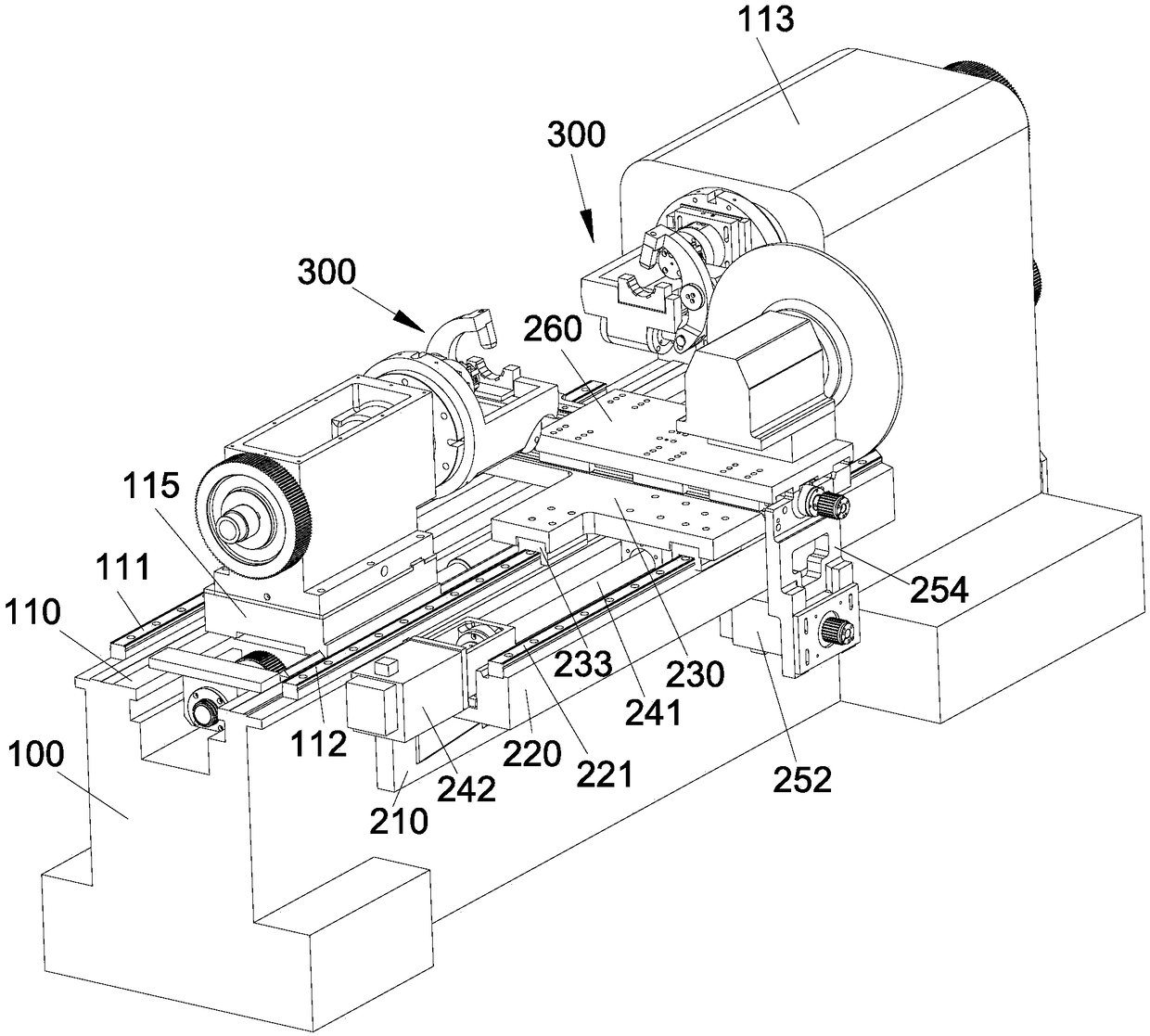
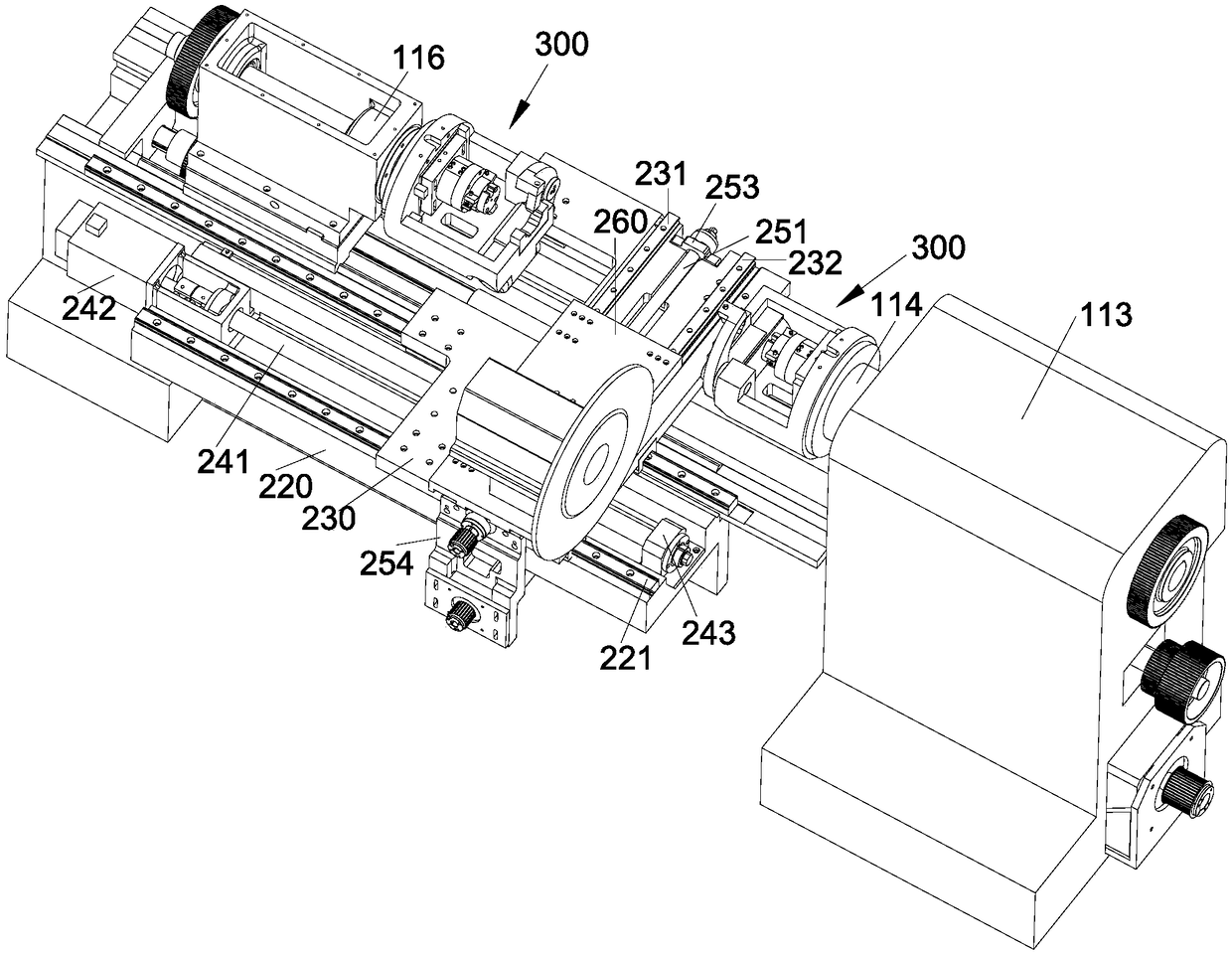
[0031] Below in conjunction with accompanying drawing, the present invention will be further described, as appended figure 1 - attached Figure 11 As shown: this embodiment provides a special machine tool for processing crankshaft pins, including: a bed 100 for installing machine tool parts, the bed 100 is provided with a working table 110; a spindle box 113, and the spindle box 113 is fixed on the bed 100, the headstock 113 is provided with a first spindle 114 and a fi...


PUM


Abstract

The invention discloses a machine tool special for machining a crankshaft connecting rod neck. The machine tool comprises a machine body, a main shaft box, a tailstock, a clamp set, a tool apron, andan inclined supporting device; the machine body comprises a working table board; the clamp set comprises a pair of clamp assemblies used for carrying out end part positioning on a crankshaft; each clamp assembly is cooperatively provided with an indexing assembly, the indexing assembly comprises an indexing plate and a positioning plate fixedly connected with the indexing plate, the indexing plateis fixedly connected with the end part of the crankshaft, and the positioning plate is rotationally connected with the clamp assembly; the tool apron is used for being connected with a tool assembly;and the inclined supporting device comprises a tool apron driving device and a supporting panel, wherein the tool apron driving device is used for driving the tool apron to move along the supportingpanel and the working table board, and the supporting panel is used for bearing the tool apron. According to the machine tool special for machining the crankshaft connecting rod neck, feeding and discharging can be facilitated, the indexing operation can be carried out rapidly and accurately, the production efficiency can be improved, the stability of the tool apron can be improved, the accuracy of positioning and the stability of fixing of clamps can be improved, and the machining precision can be improved.

Description

technical field [0001] The invention belongs to the technical field of machine tools, and in particular relates to a special machine tool for processing crankshaft connecting rod journals. Background technique [0002] Crankshaft machine tools are used to process crankshafts. The existing crankshaft machine tools have the following problems: (1) When working, the operator is located on the side of the slide box, and the fixture is located on the side away from the slide box. The car lifts the crankshaft over the slide box and then lowers it to the fixture positioning device, which is inconvenient for loading and unloading, which seriously affects the processing efficiency; (2) The existing tool holder is fixed on the slide box, and the slide box is fixed on the side of the bed The unbalanced supporting force of the bed on the sliding crate makes the force on the tool post unbalanced, and deviations are prone to occur during the machining process, resulting in poor machining ...

Claims


Application Information

Patent Timeline
Patent Type & Authority Applications(China)
IPC IPC(8): B23D79/00B23Q3/12B23Q16/06B23Q5/40B23Q1/01B23Q1/26
CPCB23D79/00B23Q1/017B23Q1/26B23Q3/12B23Q5/40B23Q16/06B23Q2703/04B23Q2703/105
Inventor 熊恒中文建军钟雪峰杨扬
Owner SICHUAN FEIYA AUTO PARTS CO LTD
Why Eureka
Try Eureka