
Online detection method for solidified bottom end position in bloom continuous casting production process

A production process and solidification end technology, applied in the field of bloom production, can solve the problems of waveform attenuation, increase of signal-to-noise ratio, large difference in echo of electromagnetic ultrasonic thickness measurement, etc.

Active Publication Date: 2015-04-08
NORTHEASTERN UNIV
View PDF10 Cites 19 Cited by
  • Summary
  • Abstract
  • Description
  • Claims
  • Application Information

AI Technical Summary

Problems solved by technology

Most of the above studies are carried out on the slab continuous casting production process using the sector mechanism. In the process of pressure feedback detection, since the slab continuous casting mostly adopts the inner and outer arcs of the sector to form a taper for pressing, most of the pressure feedback data detected is the average feedback force on a pressing surface, it is often difficult to accurately locate the specific position of the solidification end in the pressing surface
The electromagnetic ultrasonic method is limited by the large difference and poor measurability of electromagnetic ultrasonic thickness measurement echoes at high temperatures, severe waveform attenuation under large sizes, and technical bottlenecks such as increased signal-to-noise ratio, which often cannot be predicted stably.

Method used


Image

  • Online detection method for solidified bottom end position in bloom continuous casting production process
  • Online detection method for solidified bottom end position in bloom continuous casting production process
  • Online detection method for solidified bottom end position in bloom continuous casting production process

Examples


Embodiment 1

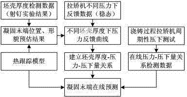
[0065] The technical scheme of the embodiment of the present invention is as figure 1 shown, follow the steps below:

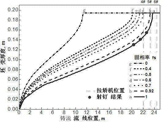
[0066] (1) In this embodiment, under the condition of casting temperature of 1486-1496°C and casting speed of 0.45m / min, the nail-shooting method is used to inject steel nails with sulfide into the casting slab of a certain mine steel type, and the steel The composition of the seed is shown in Table 1. Trimming the nailing position after solidification of the cast slab, the diffusion law of the sulfide along the direction of the casting flow is obtained through sulfur printing, and the thickness of the solidified billet shell and the liquid-solid value at the nailing position are obtained. the thickness of the two-phase region;

[0067] (2) Under the specific casting conditions obtained in step (1), the heat tracing calculation model is established based on the finite difference method. During the casting and casting process, the timing of the continuous "bi...


PUM


Abstract

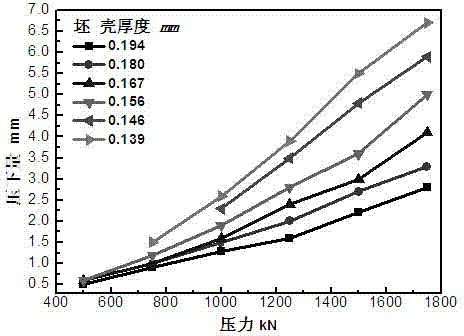
The invention belongs to the technical field of bloom production and particularly relates to an online detection method for a solidified bottom end position in the bloom continuous casting production process. The online detection method comprises the following steps: first, measuring solidified bloom shell thicknesses by a nail shooting process, establishing a thermal tracking model, calculating to obtain the pre-measurement results of the bloom shell thicknesses at different solid ratios, at different casting temperatures and at different drawing rates in the strand direction, then measuring the rolling reductions of different bloom shell thickness parts when the blooms are rolled by withdrawal and straightening units, establishing a relation curve of bloom shell thickness, pressure and rolling reduction, and establishing a corresponding relational database of steel type, bloom shell thickness, pressure and rolling reduction; in the actual production process, measuring on line when periodical rolling is carried out by each withdrawal and straightening unit, comparing the corresponding relational data of steel type, pressure and rolling reduction with the database, judging the actual bloom shell thickness of the current continuously cast bloom and determining the solidified bottom end position. The method is tightly combined with bloom continuous casting production reality, detection equipment does not need to be increased, and the online detection process of the solidified bottom end is finished by the existing withdrawal and straightening unit.

Description

technical field [0001] The invention belongs to the technical field of bloom production, and in particular relates to an online detection method for solidification end position in the bloom continuous casting production process. Background technique [0002] The characteristics of continuous casting slab solidification determine that it is easy to form central segregation and porosity during the solidification process. Calculation of solidification end depression is an effective means to solve this problem and has been widely used. The continuous casting slab solidification end reduction technology refers to applying a certain pressure at the continuous casting slab solidification end to force the liquid core in the two-phase region of the slab to deform, thereby squeezing out the steel rich in solute segregation elements at the solidification front to the liquid phase region. Simultaneously compensates for coagulation shrinkage. Reduction interval, reduction amount, reduc...

Claims


Application Information

Patent Timeline
IPC IPC(8): B22D11/16
CPCB22D11/16
Inventor 祭程朱苗勇
Owner NORTHEASTERN UNIV
Learn More