Sealing device for laser welding

A sealing device and laser welding technology, which is applied in laser welding equipment, welding equipment, metal processing equipment, etc., can solve the problems that structural parts cannot bear pressure, etc., and achieve the effect of ensuring the sealing effect, solving the pressure bearing problem, and uniform pressure distribution

Active Publication Date: 2016-05-18
哈尔滨工大焊接科技有限公司
View PDF5 Cites 0 Cited by
  • Summary
  • Abstract
  • Description
  • Claims
  • Application Information

AI Technical Summary

Problems solved by technology

[0003] The present invention aims to solve the problem that the existing light-transmitting glass used for laser welding cannot complete multi-position continuous laser welding of structural parts and cannot withstand pressure during vacuuming and argon filling, and further provides a sealing device for laser welding

Method used


Image

  • Sealing device for laser welding
  • Sealing device for laser welding
  • Sealing device for laser welding

Examples


specific Embodiment approach 1

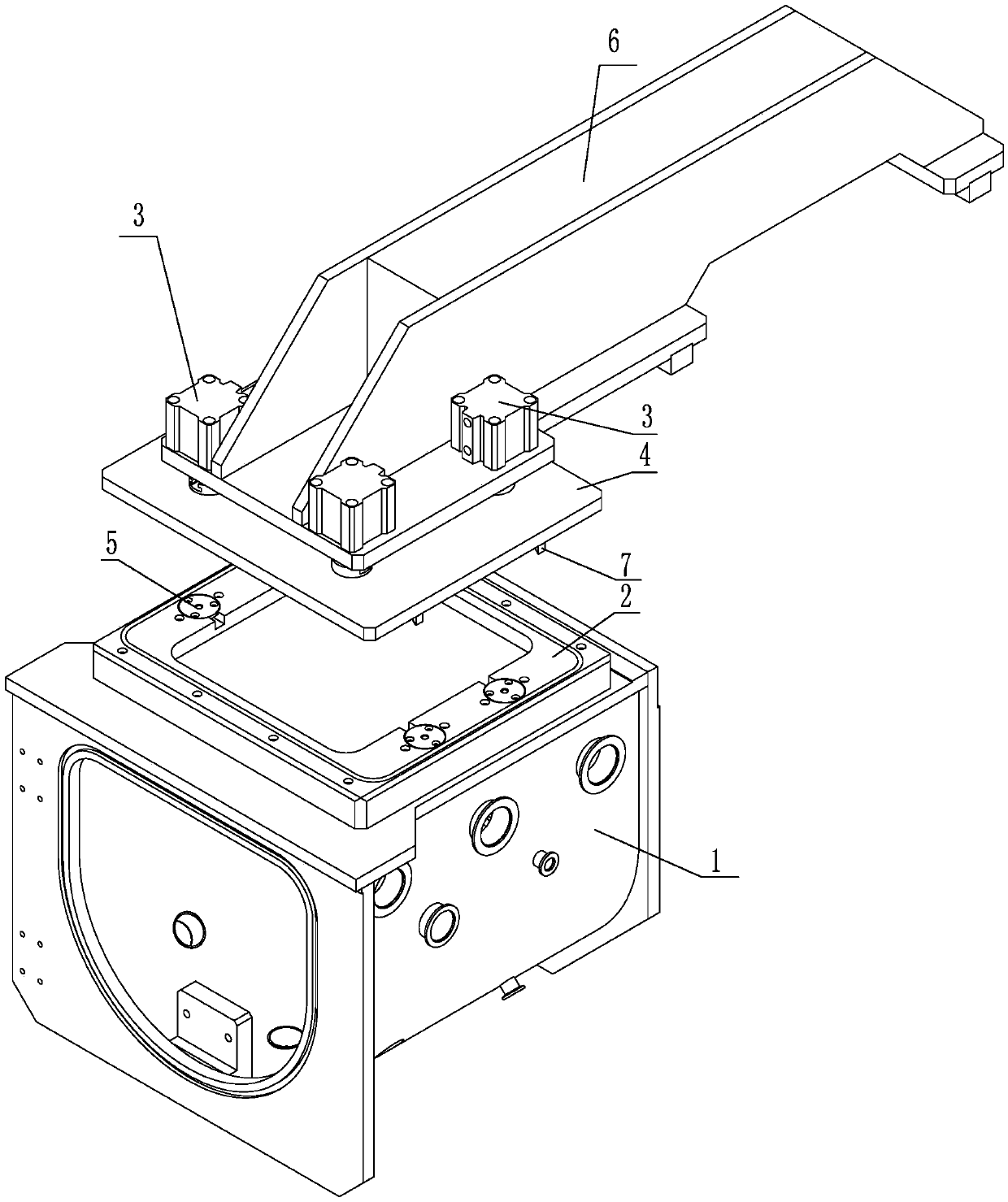
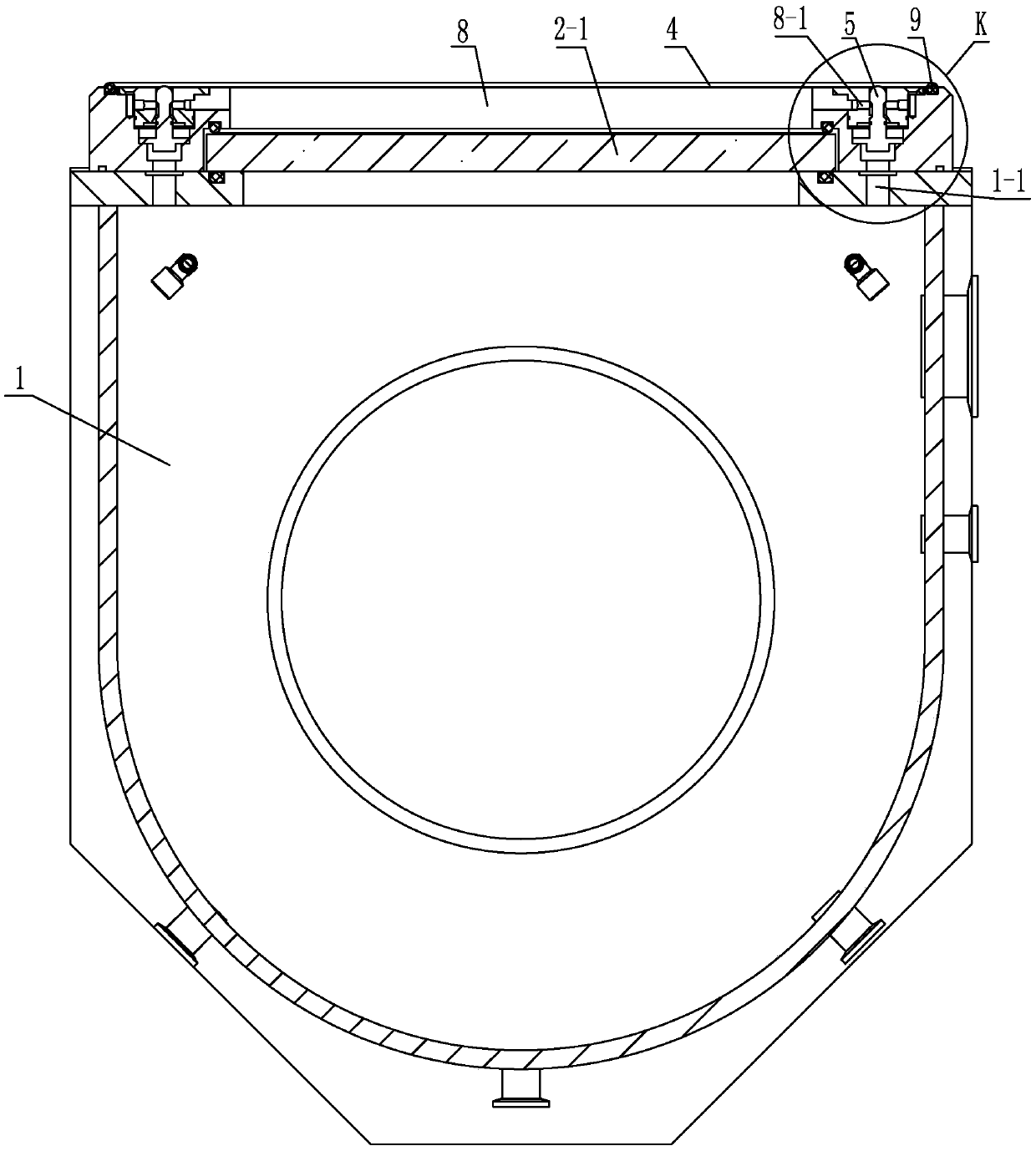
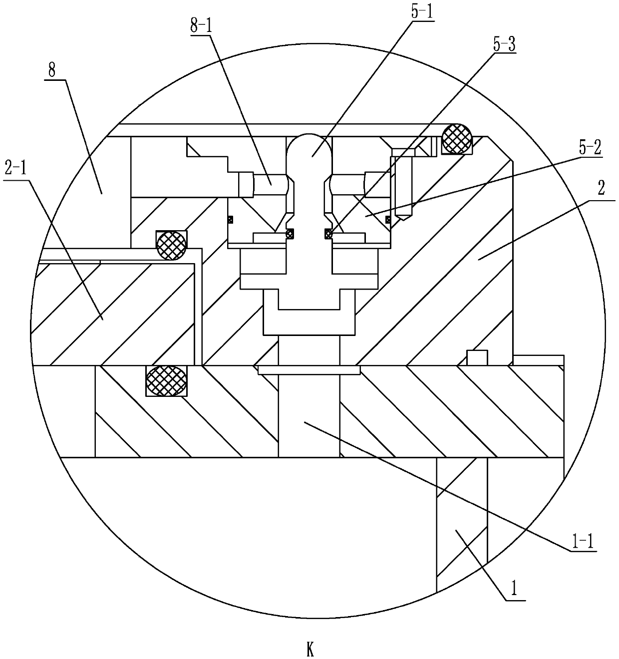
[0008] Specific implementation mode one: combine Figure 1-Figure 3 Explain that the sealing device for laser welding in this embodiment includes a vacuum chamber 1 and a mounting frame 2 for fixing a light-transmitting glass plate, and is characterized in that it also includes a cylinder fixing seat 6, a sealing cover plate 4, and N cylinders 3 , N slide valves 5 and N push rods 7, wherein N is an even number;

[0009] The middle part of the upper wall of the vacuum chamber 1 is embedded with a mounting frame 2 for fixing a light-transmitting glass plate, and N cylinders 3 are evenly distributed along its circumference on the cylinder fixing seat 6, and the ends of the driving rods of the N cylinders 3 are fixed. On the sealing cover plate 4, the driving direction of the driving rod of the cylinder 3 is downward and perpendicular to the plate surface of the sealing cover plate 4, N slide valves 5 are evenly distributed on the edge of the mounting frame 2 of the fixed transpar...

specific Embodiment approach 2

[0016] Specific implementation mode two: combination figure 1 To illustrate, the number of cylinders 3 in this embodiment is four. With such setting, it is easy to use, and multi-point pressing ensures the sealing effect. Others are the same as in the first embodiment.

specific Embodiment approach 3

[0017] Specific implementation mode three: combination figure 1 and figure 2 Note that the transparent glass plate 2-1 of this embodiment is a cuboid quartz transparent glass plate, the length of the transparent glass plate 2-1 is 355 mm, the width is 335 mm, and the height is 20 mm. With such arrangement, the light-transmitting glass plate is firm, stable and strong. Others are the same as in the first or second embodiment.


PUM

PropertyMeasurementUnit
lengthaaaaaaaaaa
widthaaaaaaaaaa
heightaaaaaaaaaa

Abstract

The invention provides a sealing device for laser welding, and relates to a sealing structure. The device solves the problems that the multi-position continuous laser welding of structural members cannot be completed and the pressure bearing cannot be realized in the processes of vacuum pumping and argon filling for the existing laser welding by using transparent glass. The device comprises a vacuum chamber and a mounting frame which is fixedly provided with a transparent glass plate, and also comprises an air cylinder fixing seat, a sealing cover plate, N air cylinders, N slide valves and N push rods, wherein the mounting frame which is fixedly provided with the transparent glass plate is inserted into the middle of the upper wall of the vacuum chamber; the N air cylinders are uniformly distributed on the air cylinder fixing seat in the circumferential direction, and the end parts of driving rods of the N air cylinders are fixedly mounted on the sealing cover plate; the N slide valves are uniformly distributed on the edge of the mounting frame which is fixedly provided with the transparent glass plate, each slide valve comprises a valve rod, a valve body and a sealing ring, the sealing rings are fixedly mounted on the valve rods, the valve rods are vertically mounted in the valve bodies in a sliding manner, and the sealing rings are bonded with inner cavities of the valve bodies. The device is used for laser welding.

Description

technical field [0001] The invention relates to a sealing structure, in particular to a sealing device for laser welding. Background technique [0002] When welding metals with strong chemical activity, such as beryllium and zirconium, in order to avoid the adverse effects of water and oxygen in the welding atmosphere on the weld formation and corrosion resistance, a sealed cabin must be used to control the welding atmosphere to achieve good protection. Effect. Conventional vacuum chambers used for laser welding have very strict requirements on the performance and size of the light-transmitting glass plate due to the excessive pressure difference between the inside and the outside. Although the small size of the light-transmitting glass can solve the problem of pressure bearing, it cannot complete the multi-position continuous laser of structural parts. welding. However, the large size of the light-transmitting glass may cause damage due to excessive pressure during the va...

Claims


Application Information

Patent Timeline
Patent Type & Authority Patents(China)
IPC IPC(8): B23K26/12
CPCB23K26/1224B23K26/123
Inventor 陈彦宾闫相和陶汪李俐群蔡创刘宏任李纵跃林泳
Owner 哈尔滨工大焊接科技有限公司
Why Eureka
Try Eureka