
Workbench for grabbing and separating stacked parts

A workbench and parts technology, applied in the field of parts separation and lifting equipment, can solve the problems of high labor intensity, difficulty in manual separation, hidden safety hazards of moving personnel, etc., and achieve the effect of reducing labor intensity and avoiding work-related injuries

Active Publication Date: 2015-04-08
WUHU YINXING AUTO PARTS
View PDF5 Cites 14 Cited by
  • Summary
  • Abstract
  • Description
  • Claims
  • Application Information

AI Technical Summary

Problems solved by technology

[0002] When storing or transporting disc parts, especially disc cover stamping parts, in order to save space, the method of stacking the disc covers is often used. However, the stacked disc cover parts, such as flanges, due to the quality Heavy, manual handling and separation is labor-intensive, low separation efficiency, and has certain safety hazards for moving personnel, especially for flat flanges, there is no gap between layers of flat flanges stacked together, and it is difficult to separate them by hand , in order to facilitate the user to pick up the parts, it is necessary to place the parts within an appropriate height range. In the prior art, the parts are separated manually and placed on a special shelf with an appropriate height. The labor intensity is high and it is also not conducive to Workers' Personal Safety
[0003] The same is true for stamped plate parts. Due to the small thickness of stamped disc cover parts and the slight gap between layers, it is difficult to separate them by hand, which is not conducive to improving production efficiency, and the sharp edges of stamped parts easy to scratch the carrier

Method used


Image

  • Workbench for grabbing and separating stacked parts
  • Workbench for grabbing and separating stacked parts
  • Workbench for grabbing and separating stacked parts

Examples


Embodiment Construction

[0031] In order to make the technical means, creative features, goals and effects achieved by the present invention easy to understand, the present invention will be further described below in conjunction with specific illustrations.

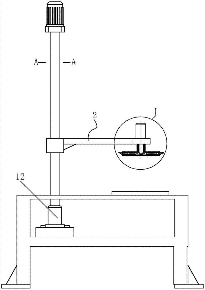
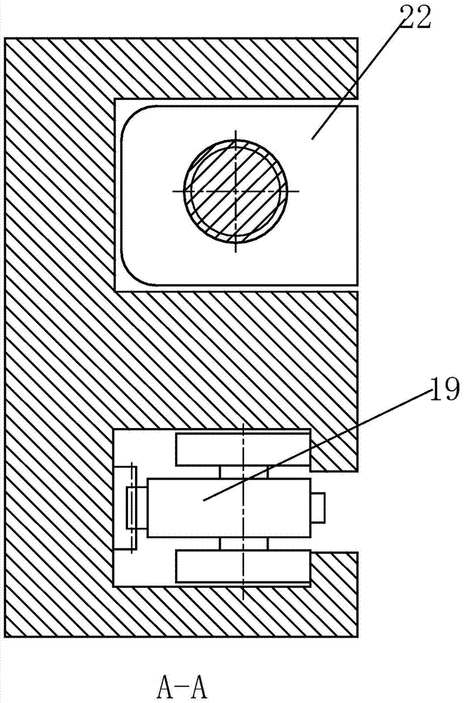
[0032] Such as Figure 1 to Figure 13 As shown, a workbench for grabbing and separating stacked parts includes a bearing workbench 1 for placing parts, a grabbing arm 2 for grabbing parts, and a handle for rotating the grabbing arm 2 and parts. A rotating column 3 is located on the left side of the carrying table 1 , and one end of the grasping cantilever 2 is sleeved on the rotating column 3 .

[0033] The middle part of the bearing workbench 1 is provided with a central support plate 9, the left side of the upper end surface of the bearing workbench 1 is provided with a No. 1 through hole 10, and the right side of the upper end surface of the bearing workbench 1 is provided with a base plate for placing and fixing parts. 11. The base plate 11...


PUM


Abstract

The invention relates to a workbench for grabbing and separating stacked parts. The workbench comprises a bearing workbench, a grabbing cantilever and a rotating vertical column, wherein a central support plate is arranged in the middle of the bearing workbench, a through hole I is formed in the left side of the upper end surface of the bearing workbench, a base support plate is arranged on the right side of the upper end surface of the bearing workbench, a motor I is arranged on the left side of the central support plate, the rotating vertical column is driven by the motor I to rotate through the transmission of a gear, a vertical column sleeving block is arranged on the rotating vertical column, a bearing is arranged on the vertical column sleeving block in a sleeving way, an outer ring of the bearing is clamped in the through hole I, a groove I and a groove II are formed in the right side surface of the rotating vertical column in parallel, a rack is arranged on the inner side surface of the groove I, a lever is arranged in the groove II, and the upper end of the lever is connected with a motor II. The bearing workbench is used as a support, and the stacked parts are grabbed and separated by the grabbing cantilever capable of rotating and lifting on the bearing workbench, so that the labor intensity of workers is reduced, and the workers are prevented from being injured during separation of sharp or heavy parts.

Description

technical field [0001] The invention relates to the technical field of parts separation and lifting equipment, in particular to a grasping and separation workbench for stacked parts. Background technique [0002] When storing or transporting disc parts, especially disc cover stamping parts, in order to save space, the method of stacking the disc covers is often used. However, the stacked disc cover parts, such as flanges, due to the quality Heavy, manual handling and separation is labor-intensive, low separation efficiency, and has certain safety hazards for moving personnel, especially for flat flanges, there is no gap between layers of flat flanges stacked together, and it is difficult to separate them by hand , in order to facilitate the user to pick up the parts, it is necessary to place the parts within an appropriate height range. In the prior art, the parts are separated manually and placed on a special shelf with an appropriate height. The labor intensity is high and...

Claims


Application Information

Patent Timeline
IPC IPC(8): B25J9/02B25J9/14
Inventor 曹志刚
Owner WUHU YINXING AUTO PARTS
Learn More