Single magnetic type permanent magnet track braking device

A brake device and track technology, which is applied in the direction of brakes interacting with brake components and tracks, railway brake systems, transportation and packaging, etc., can solve problems such as the influence of braking accuracy and slow braking response, and achieve high resolution problems, pole piece life extension, and effective frictional braking force improvement

Inactive Publication Date: 2015-04-08
华伍轨道交通装备(上海)有限责任公司
View PDF6 Cites 7 Cited by
  • Summary
  • Abstract
  • Description
  • Claims
  • Application Information

AI Technical Summary

Problems solved by technology

The above-mentioned braking methods must be allocated by the control unit through the energy of the solenoid valve or vacuum pump, and then the braking function is realized through the basic brake actuator. The braking process is affected by electrical conversion, electro-hydraulic conversion, air action and mechanical structure. Delay, slow braking response, braking accuracy is affected

Method used


Image

  • Single magnetic type permanent magnet track braking device
  • Single magnetic type permanent magnet track braking device
  • Single magnetic type permanent magnet track braking device

Examples


Embodiment Construction

[0031] The specific implementation of the single magnet permanent magnet track brake device of the present invention will be described in detail below in conjunction with the accompanying drawings.

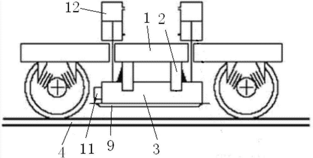
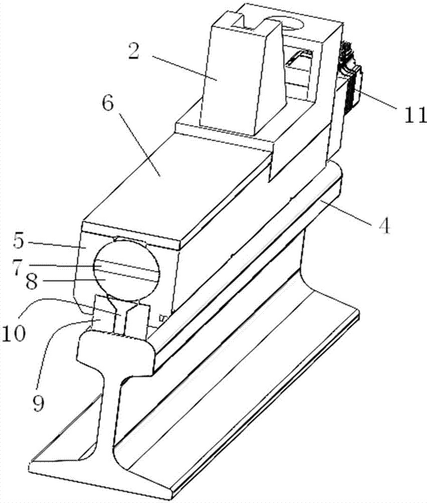
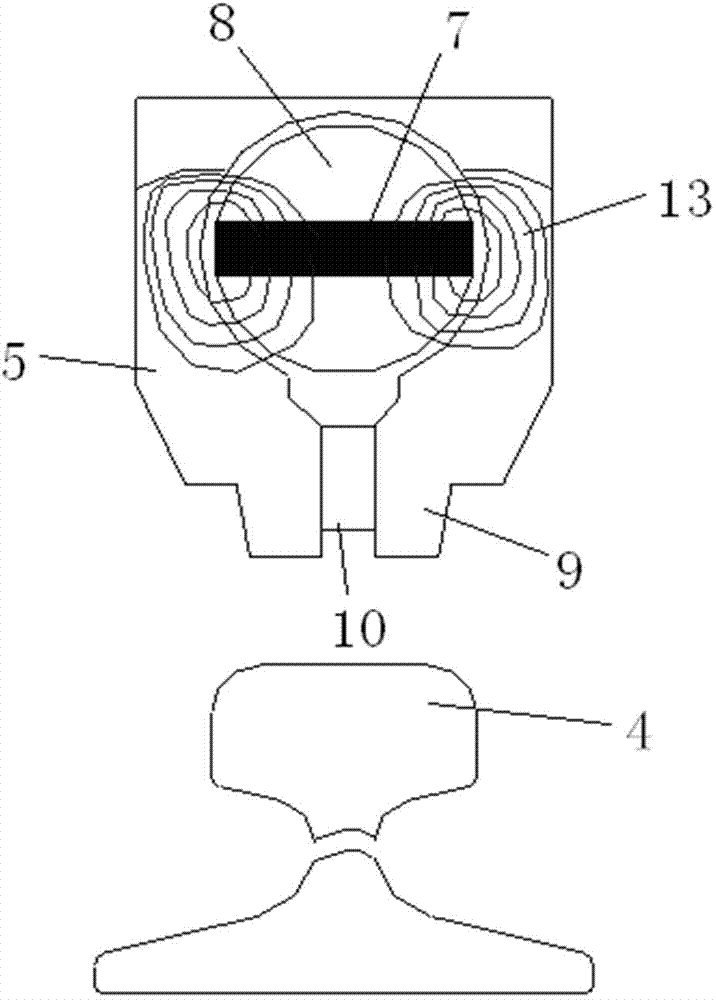
[0032] See attached figure 1 , 2 , Single-magnetic permanent magnet track brake device, involving the circuit, magnetic field, friction material and mechanical movement parts, including the bogie 1 and the brake magnet 3 connected by the force transmission mechanism 2 under the bogie 1, the brake magnet 3 and the track There is a distance between the steel rails 4. The brake magnet 3 includes side plates 5 on both sides. The length direction of the side plates 5 is the same as the track direction. A cover plate 6 is provided above the side plate 5. A through hole is formed between the side plate 5 and the cover plate 6 is a non-magnetic material. The permanent magnet 7 is arranged in a low-carbon steel column 8 to form a magnetic shaft. There is an air gap between the steel column 8 a...


PUM


Abstract

The invention relates to the technical field of rail transit trains and discloses a single magnetic type permanent magnet track braking device, which comprises a bogie. The single magnetic type permanent magnet track braking device is characterized in that a braking magnet is connected to the bottom of the bogie through a force transmission mechanism; a distance exists between the braking magnet and a rail of the track; the braking magnet comprises side plates on both sides; the length direction of the side plates is the same as the direction of the track; a cover plate is arranged on the top of the side plates; a through hole is formed among the side plates and the cover plate; the side plates are made of a magnetic material; the cover plate is made of a nonmagnetic material; an elongated permanent magnet is arranged in the through hole; magnetic poles of the permanent magnet are the upper and lower surfaces thereof; pole shoes are arranged under the side plates; a nonmagnetic gap is formed between the pole shoes; a driving device is arranged at one ends of the side plates and is used for driving the permanent magnet to rotate. According to the invention, simple and reliable control over the magnetic strength of the magnet and the rail is realized by changing the direction of the magnetic field of the permanent magnet.

Description

Technical field [0001] The invention relates to the technical field of rail transit trains, in particular to a single-magnetic permanent magnet track brake device. Background technique [0002] In the transportation design and operation management of rail trains, the problem of train braking has always been a very important and complex issue. In order to ensure safety during the operation of the train, it is necessary to ensure that the train can brake within the specified braking distance. [0003] Rail train braking methods generally include electro-pneumatic braking, electro-hydraulic braking, vacuum braking and so on. The above-mentioned braking methods need to pass through the control unit to realize the deployment of power source through solenoid valve or vacuum pump energy, and then realize the braking function through the basic brake actuator. The braking process is subject to electrical conversion, electro-hydraulic conversion, air action and mechanical structure. The br...

Claims


Application Information

Patent Timeline
Patent Type & Authority Applications(China)
IPC IPC(8): B61H7/08
CPCB61H7/08
Inventor 裴玉春卢笑山冯夫磊王鹏
Owner 华伍轨道交通装备(上海)有限责任公司
Why Eureka
Try Eureka