Injection-molded packing case for liquid crystal display panels
A technology for liquid crystal panels and packaging boxes, applied in packaging, transportation and packaging, packaging of fragile items, etc., can solve the problems of increasing packaging costs, corporate losses, and deformation of liquid crystal panels, increasing bending strength, increasing recycling times, The effect of reducing packaging costs
- Summary
- Abstract
- Description
- Claims
- Application Information
AI Technical Summary
Problems solved by technology
Method used
Image

Examples
Embodiment 1
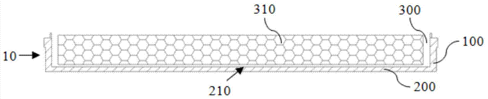
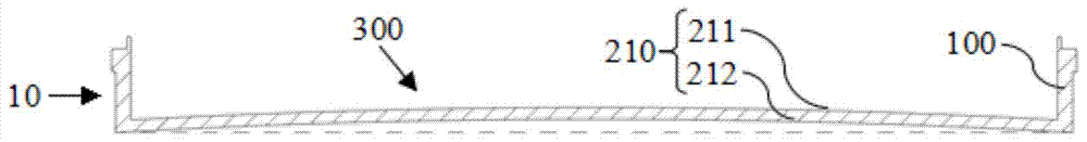
[0025] refer to figure 2 , the protruding structure 210 is composed of an upper surface 211 and a lower surface 212. In this embodiment, the upper surface 211 and the lower surface 212 are both arc-shaped surfaces convex upward. When carrying the liquid crystal panel, the liquid crystal panel first contacts the upper surface 211 of the raised structure 210, and the arc-shaped raised structure 210 generates yield stress to support the liquid crystal panel. stacked so that the gravity of the liquid crystal panel is greater than the yield stress of the protruding structure 210, when the liquid crystal panel is placed in the box body 10, the effect of the protruding structure 210 protruding into the box body 10 is offset, and the protruding structure 210 is flat The panel does not affect the flatness of the liquid crystal panel placed in the box 10 . When the liquid crystal panel is removed from the box body 10 , the yield strength of the raised structure 210 ensures that the ra...
Embodiment 2
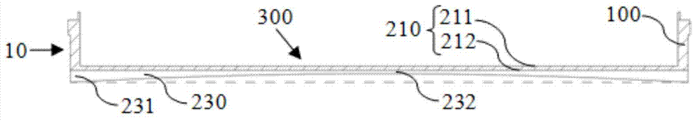
[0027] refer to image 3 , Figure 4 The upper surface 211 of the protruding structure 210 is an upwardly convex arc surface or a plane, the lower surface 212 is a plane, and several reinforcing ribs 230 are arranged on the outer side of the lower surface 212 . In this embodiment, the upper surface of the raised structure 210 is a plane. The rib 230 includes a rigid end 231 and a flexible end 232. The rigid end 231 is located on both sides of the rib 230, and the flexible end 232 is located in the middle of the rib 230. The height of the rigid end 231 is greater than that of the flexible end 232 , so that the outer edge of the rib 230 is a circular arc concave along the outside of the box body 10 toward the inside of the box body 10 , so that the protruding structure 210 is in the shape of a concave lens. Since the height of the rigid end 231 is greater than the height of the flexible end 232, the surrounding strength of the bottom panel 200 of the box body 10 is greater than...
Embodiment 3
[0029] refer to Figure 5 In this embodiment, the upper surface 211 of the protruding structure 210 is an upwardly convex arc surface, and the lower surface 212 is a plane. Each reinforcing rib 230 is provided on the lower surface 212 and is located outside the bottom panel 200 . Since the upper surface 211 of the protruding structure 210 is an upwardly convex arc surface, and the lower surface is connected with a concave reinforcing rib 230, it has a double suppression effect on the concave problem at the bottom of the box body 10, so that the box body 10 has a more Good yield strength has a better technical effect on preventing the bottom of the packaging box from sinking, and is suitable for packaging boxes carrying large-size LCD panels.
[0030] To sum up, the injection molding packaging box for liquid crystal panels provided by the present invention has a simple structure, increases the bending strength of the injection molding packaging box, solves the problem of the co...
PUM
 Abstract
Description
Claims
Application Information
 - R&D
- Intellectual Property
- Life Sciences
- Materials
- Tech Scout
- Unparalleled Data Quality
- Higher Quality Content
- 60% Fewer Hallucinations
Browse by: Latest US Patents, China's latest patents, Technical Efficacy Thesaurus, Application Domain, Technology Topic, Popular Technical Reports.
© 2025 PatSnap. All rights reserved.Legal|Privacy policy|Modern Slavery Act Transparency Statement|Sitemap|About US| Contact US: help@patsnap.com