Intelligent self-detection brake for traction machine

A mechanical brake and self-inspection technology, which is applied in hoisting devices and other directions, can solve the problems of complex installation, accelerated friction plate damage, and fast friction plate damage, and achieves the effects of firm connection, increased mutual friction, and reduced wear speed

Active Publication Date: 2015-04-08
SICHER ELEVATOR
View PDF6 Cites 18 Cited by
  • Summary
  • Abstract
  • Description
  • Claims
  • Application Information

AI Technical Summary

Problems solved by technology

During the engagement process of the brake shoe assembly and the brake wheel, the friction plate of the brake shoe assembly heats up very rapidly. If the temperature is not cooled in time, the friction plate will be easily damaged due to continuous engagement for a long time; and the traction machine is installed in the external environment , Dust, impurities, etc. are easy to fall on the brake wheel of the traction machine, thereby affecting the cohesion between the brake wheel and the brake shoe assembly, and it is easy to scratch the surface of the brake wheel and the friction plate during the cohesion process
Moreover, the brake shoe assembly is continuously engaged and separated from the brake wheel for a long time, which leads to serious wear of the brake shoe assembly. The friction plate on the brake shoe assemb

Method used


Image

  • Intelligent self-detection brake for traction machine
  • Intelligent self-detection brake for traction machine
  • Intelligent self-detection brake for traction machine

Examples


Example Embodiment

[0013] The present invention will be further described below in conjunction with the drawings and embodiments, but it is not a basis for limiting the present invention.
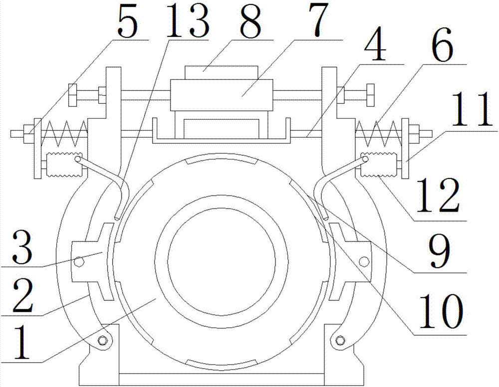
[0014] The embodiment of the present invention: an intelligent self-detecting traction machine brake, as attached Figure 1-3 As shown, it includes a brake wheel 1 located at the head end of the traction machine housing. A brake arm 2 is provided on both sides of the brake wheel 1. The lower end of the brake arm 2 is installed on the base of the traction machine. Each brake arm 2 is connected with a brake shoe assembly 3, and a brake rod 4 penetrates through the upper end of each brake arm 2. The head end of the brake rod 4 is provided with an adjusting nut 5, which is connected to the There is a brake spring 6 on the rod between the brake arms 2, and a magnet 7 is arranged above the brake wheel 1. The magnet 7 is installed on the base of the magnet. The two ends of the magnet 7 are connected to each other throu...


PUM


Abstract

The invention discloses an intelligent self-detection brake for a traction machine. The intelligent self-detection brake comprises a brake wheel positioned at the head end of the casing of the traction machine, two brake arms are respectively arranged on both sides of the brake wheel, a brake block assembly is connected to each brake arm, a brake rod is arranged at the upper end of each brake arm, an adjusting nut is arranged at the head end of each brake rod, a brake spring is arranged on the rod body between the adjusting nut and the corresponding brake arm, a magnetic device is arranged above the brake wheel, two head ends of the magnetic device are respectively connected with the brake arms, and a controller is arranged on the casing at the rear end of the magnetic device, of the traction machine; grooves are formed in the ring body of the brake wheel, and friction resisting blocks are arranged in the grooves respectively; each brake block assembly comprises a brake block, a clamp groove is formed in the brake block, a concave pit is formed in the brake block at the bottom of the clamp groove, a leading-out groove is also formed in the brake block near the concave pit, an I-shaped friction plate is arranged in the clamp groove, a bulge is formed at the bottom of the I-shaped friction plate, a pressure sensor is arranged in the concave pit, and the leading wire of the pressure sensor is arranged in the leading-out groove.

Description

technical field [0001] The invention relates to a traction machine brake used for an elevator traction machine, in particular to an intelligent self-detection traction machine brake. Background technique [0002] When the existing traction machine brakes are used, the brake shoe assembly is used to interact with the brake wheel to control the rotation of the traction machine. During the engagement process of the brake shoe assembly and the brake wheel, the friction plate of the brake shoe assembly heats up very rapidly. If the temperature is not cooled in time, the friction plate will be easily damaged due to continuous engagement for a long time; and the traction machine is installed in the external environment , Dust, impurities, etc. are easy to fall on the brake wheel of the traction machine, thereby affecting the cohesion between the brake wheel and the brake shoe assembly, and it is easy to scratch the surface of the brake wheel and the friction plate during the cohesi...

Claims


Application Information

Patent Timeline
IPC IPC(8): B66D5/08B66D5/30
CPCB66D5/08B66D5/30B66D2700/03
Inventor 茹晓英沈建学牛有权吴郁李徐方飞周国平嵇剑伟
Owner SICHER ELEVATOR
Why Eureka
Try Eureka