Boom rack and dynamic compaction machine

A technology of dynamic tamping machines and booms, which is applied in the field of booms and dynamic tamping machines, and can solve problems such as large deformation of the boom, uneven force, and restrictions on the bearing capacity of the boom

Active Publication Date: 2015-04-08
ZHEJIANG SANY EQUIP
View PDF6 Cites 1 Cited by
  • Summary
  • Abstract
  • Description
  • Claims
  • Application Information

AI Technical Summary

Problems solved by technology

During the working process of the lattice arm 1', the center line a' of the boom, the action line b' of the hoisting weight and the action line c' of the luffing cylinder form a typical cantilever beam structure, so that the hoisting weight 4' has a relatively large impact on the lattice arm 1'. The large bending moment makes the main chords, web pipes and joints of the boom unevenly stressed, and the boom deforms greatly, which seriously restricts the bearing capacity of the boom

Method used


Image

  • Boom rack and dynamic compaction machine
  • Boom rack and dynamic compaction machine
  • Boom rack and dynamic compaction machine

Examples


Embodiment Construction

[0027] It should be noted that, in the case of no conflict, the embodiments of the present invention and the features in the embodiments can be combined with each other. Below in conjunction with accompanying drawing, each preferred embodiment of the present invention is described further:

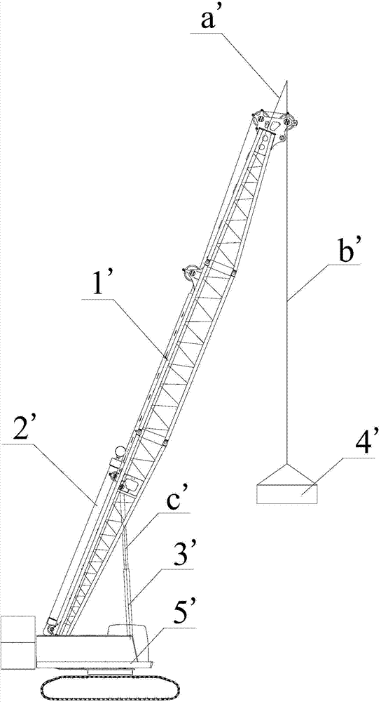
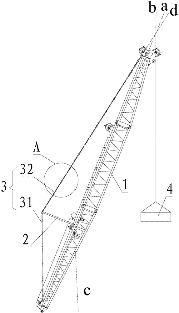
[0028] See figure 2 , the figure shows the structure of the jib provided by the embodiment of the present invention, the jib is used for a dynamic compaction machine, specifically including:

[0029] Truss arm 1;

[0030] A strut 2, the bottom end of which is connected to the truss arm 1;

[0031] Tensioning mechanism 3, one end of which is connected to the arm tail of truss arm 1, and the other end is connected to the arm head of truss arm 1 after being supported by the above-mentioned strut 2;

[0032] Moreover, the struts 2 and the tensioning mechanism 3 are both arranged on the side of the lattice arm 1 away from the hoisting weight 4 .

[0033] In the jib structure provided by th...


PUM


Abstract

The invention discloses a boom rack and a dynamic compaction machine. The boom rack comprises a truss boom, a support rod and a tensioning mechanism, wherein the bottom end of the support rod is connected with the truss boom; one end of the tensioning mechanism is connected with a boom tail of the truss boom; the other end of the tensioning mechanism is supported by the support rod and is connected with a boom head of the truss boom; the support rod and the tensioning mechanism are arranged on the side, far from a crane, of the truss boom. The boom rack provided by the invention has the advantages of high carrying capacity and long service life.

Description

technical field [0001] The invention relates to the field of engineering machinery, in particular to an arm frame and a dynamic compaction machine. Background technique [0002] The dynamic tamping machine is mainly used for compacting the loose soil. Its working principle is roughly as follows: the lifting equipment repeatedly lifts the rammer to a certain height and then releases the rammer. The rammer falls into the soil to form a strong shock wave and high stress. This improves the strength of the foundation, reduces its compressibility, improves its anti-seismic ability, and eliminates collapsibility, etc. The dynamic compaction machine has the advantages of simple structure, short construction period and wide application range, and is widely used in civil buildings, airports, docks, expressways, artificial islands and other fields. [0003] figure 1 The structure of the existing dynamic compaction machine is shown, the arm tail of the truss arm 1' is hinged at the re...

Claims


Application Information

Patent Timeline
IPC IPC(8): E02D3/046
CPCE02D3/046
Inventor 王胜吴志强戴春龙
Owner ZHEJIANG SANY EQUIP
Why Eureka
Try Eureka