Lock pin type synchronous ring

A technology of synchronous ring and synchronous ring cone, which is applied in the direction of clutches, mechanical drive clutches, mechanical equipment, etc., can solve the problems of harsh working environment requirements, easy to fall off, low ratio, etc., achieve good oil discharge and heat dissipation performance, increase contact area, Effect of increasing sync capacity

Inactive Publication Date: 2015-04-08
LUZHOU CHANGJIANG MACHINERY
View PDF8 Cites 2 Cited by
  • Summary
  • Abstract
  • Description
  • Claims
  • Application Information

AI Technical Summary

Problems solved by technology

However, although this kind of longitudinal oil groove solves the problem that the molybdenum layer is easy to fall off at the corners, because the width of the oil groove is relatively wide, generally 5-7mm, and the depth is relatively shallow, generally 0.3-0.6mm, the ratio of groove width to groove depth is 10-18, the ratio of slot width to slot pitch is 50-60%
As a result, the effective friction surface of the cone surface of this structure (the contact area with the coupler during work) accounts for a relatively low proportion of the entire cone surface, generally 40-50%. Compared with the molybdenum sprayed friction surface before improvement, the friction coefficient of the friction surface , The friction performance (friction torque) has basically not changed, and for heavy-duty trucks, it still cannot meet the requirements of its harsh working environment

Method used


Image

  • Lock pin type synchronous ring
  • Lock pin type synchronous ring
  • Lock pin type synchronous ring

Examples


Embodiment 1

[0028] This embodiment is the high-grade synchronous ring of the present invention.

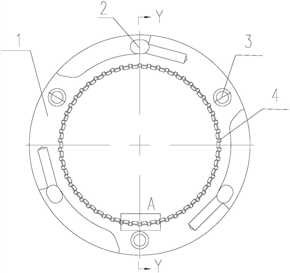
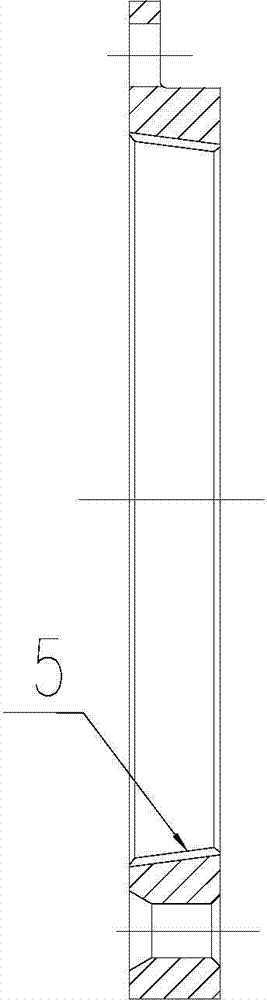
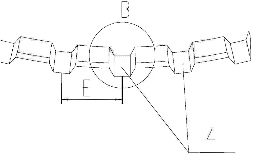
[0029] Such as Figure 1-Figure 4 As shown, the high-grade synchronous ring includes a synchronous ring end face 1 , an adjustment limit hole 2 , a connecting hole 3 , an axial oil groove 4 and a synchronous ring tapered surface 5 . Its main dimensions are: the diameter of the cone surface is 130mm; the cone surface 5 is evenly distributed with axial oil grooves 4, the groove width D is 3mm, the groove depth C is 0.9mm, the groove distance E is 7.1mm, the ratio of groove width to groove depth is 3.33, and the groove width is 3.33. The width to groove pitch ratio is 42%, the length L is 10mm; the angle θ on both sides of the oil groove is 30°. Molybdenum is sprayed on the conical surface 5 of the synchronous ring, and the thickness of the molybdenum layer is 0.1mm. The effective friction area ratio of the cone surface is 57.1%, the friction torque is 77.3N.m, and the oil discharge area is 12...

Embodiment 2

[0031] This embodiment is the low gear synchronizing ring of the present invention.

[0032] Such as Figure 5 , Figure 6 As shown, the low gear synchronous ring includes a synchronous ring end surface 1 , a connecting hole 3 , a synchronous ring tapered surface 5 and an engagement groove 6 . The diameter of the conical surface is 200mm synchronous ring, and the axial oil grooves 4 are evenly distributed on the conical surface 5; The ratio is 39%, the length is 22mm; the angle on both sides of the oil groove is 30°. Molybdenum is sprayed on the conical surface 5 of the synchronous ring, and the thickness of the molybdenum layer is 0.2mm. The effective friction area ratio of the cone surface is 60.8%, the friction torque is 95.2N.m, and the oil discharge area is 191mm 2 .

Embodiment 3

[0034] The comparative detection data of the improved synchronous ring of the embodiment of the present invention and the synchronous ring of the same specification in the prior art 3 are as follows:

[0035]

[0036] Note: The diameter of the synchronous ring cone surface of this embodiment and prior art 3 is 124mm.

[0037] Compared with the synchronous ring of the prior art, the present invention has improved effective friction area, friction torque, and oil discharge area, can improve the gear shifting performance of the synchronizer, improves the gear shifting performance of the synchronizer, and has more excellent oil discharge Heat dissipation performance, under the same conditions, the performance of withstanding the high temperature generated during work is better. Moreover, due to the increased contact area, the tapered surface wears slowly, which improves the service life of the synchronizer. It is especially suitable for the use requirements of the gearbox sy...


PUM


Abstract

The invention provides a lock pin type synchronous ring for a heavy truck transmission synchronizer. Axial oil grooves are formed in the synchronous ring taper surface, and molybdenum is sprayed on the taper surface. The width of each axial oil groove in the synchronous ring taper surface is in a range of 2.5mm to 4.5mm, and the groove depth is in a range of 0.7mm to 1.1mm. The ratio of the groove width to the groove depth is between 2 and 7, the ratio of the groove width to the groove distance is in a range of 0.35 to 0.45, and the angles on the two sides of the oil grooves are in a range of 20 degrees to 45 degrees. The synchronous ring has the advantages of being abrasion resistant and high-temperature resistant, good in oil discharge radiation performance, capable of increasing the synchronous ring service life and particularly applicable to heavy truck transmission synchronizers.

Description

technical field [0001] The invention relates to a synchronizer for a gearbox of a heavy-duty truck, in particular to a lock pin type synchronizer ring on the gearbox synchronizer. Background technique [0002] In the automobile gearbox, the function of the synchronizer is to mesh the connected gears when they reach the same speed during the shifting process of the car, so as to avoid the impact caused by the direct meshing of gears with different speeds. The synchronizer is the main component that improves the shifting performance of the car, synchronizes the main shafts with different speeds, and transmits the output torque of the engine, and the synchronizer ring is an important part of the synchronizer. [0003] At present, most of the tapered surfaces of the locking pin synchronous rings use carbon friction materials bonded to the substrate to obtain a higher average coefficient of friction. Although carbon friction materials have the advantages of high friction coeffic...

Claims


Application Information

Patent Timeline
Patent Type & Authority Applications(China)
IPC IPC(8): F16D23/04
Inventor 韦仁军
Owner LUZHOU CHANGJIANG MACHINERY
Why Eureka
Try Eureka