OWTS power cable oscillation wave test equipment and test method

An oscillatory wave test, power cable technology, applied in the direction of test circuit, test dielectric strength, fault location, etc., can solve the problems of difficult field test, long charging time, large power capacity, etc. Experimental, the effect of a large capacitance range

Active Publication Date: 2015-04-08
XI AN JIAOTONG UNIV
View PDF6 Cites 13 Cited by
  • Summary
  • Abstract
  • Description
  • Claims
  • Application Information

AI Technical Summary

Problems solved by technology

[0005] To sum up, the shortcomings of the existing power cable oscillatory wave test are: 1. The power cable is charged by the frequency conversion resonance withstand voltage test device, and the power supply capacity required by the equipment is large, heavy, and inconvenient to transport, which makes the field test difficult; 2. The DC high-voltage power supply charges the power cable, and the charging time is long, reaching several minutes, which accelerates the aging of the cable insulation

Method used


Image

  • OWTS power cable oscillation wave test equipment and test method
  • OWTS power cable oscillation wave test equipment and test method

Examples


Embodiment 1

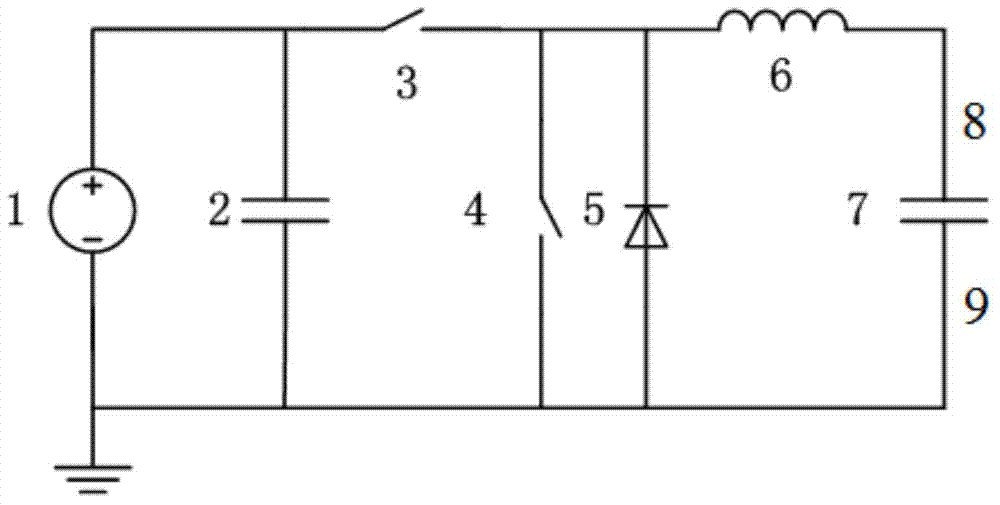
[0037] When the DC high voltage power supply 1 charges the capacitor 2 by 10kV, the capacity of the capacitor 2 is selected as 10μF, the reactor inductance is selected as 0.7H, and the capacitance of the cable to be tested is 0.05μF, the voltage on the cable can be 0.69 after the first high voltage electronic switch 3 is closed. The ms reaches 17.11kV. After the second high-voltage electronic switch 4 is closed, an attenuated oscillation wave of 851.5 Hz is formed on the cable.

Embodiment 2

[0039] When the DC high voltage power supply 1 charges the capacitor 2 by 10kV, the capacity of the capacitor 2 is selected as 20μF, the reactor inductance is selected as 0.8H, and the capacitance of the cable to be tested is 2μF, the voltage on the cable can be 0.68ms after the first high voltage electronic switch 3 is closed. Up to 16.88kV, after the second high-voltage electronic switch 4 is closed, an attenuated oscillation wave of 134.5 Hz is formed on the cable.

Embodiment 3

[0041] When the DC high voltage power supply 1 charges the capacitor 2 by 20kV, the capacitor 2 capacity is selected as 20μF, the reactor inductance is selected as 1H, and the cable capacity to be tested is 4μF, the voltage on the cable can reach 5.9ms after the first high voltage electronic switch 3 is closed. 32.7kV, after the second high-voltage electronic switch 4 is closed, an attenuated oscillation wave of 79.5 Hz is formed on the cable.


PUM


Abstract

The invention discloses OWTS power cable oscillation wave test equipment and a test method. The OWTS power cable oscillation wave test equipment comprises a DC high-voltage power supply, a capacitor, high-voltage electronic switches, an electric reactor, a backward diode and a partial discharge detection unit. The DC high-voltage power supply charges the capacitor and controls the high-voltage electronic switch to be conducted after charging is completed. A cable is charged by the capacitor via a quite short period of time, and then the other high-voltage electronic switch is controlled to be conducted. A weak damping loop is formed by the electric reactor, the cable and line resistance, and damped oscillation wave is generated. Acquisition and analysis of partial discharge signals of the cable are realized by using the partial discharge detection unit so that the insulation state of the power cable is finally acquired. The equipment is compact in structure and convenient for onsite testing, and range of cable capacity capable of being detected can be 0.05muF-6muF. Besides, the test process has no long time of DC charging on the cable so that cable insulation is not damaged.

Description

Technical field [0001] The invention relates to power cable insulation state detection technology and its application field, in particular to a power cable oscillation wave test equipment and test method. Background technique [0002] As the urban electricity load continues to grow rapidly, the requirements for power supply reliability are getting higher and higher, and the full realization of cable in the urban distribution network is the development direction of adapting to high reliability and saving space. After the power cable is put into operation, it will be affected by a variety of unfavorable factors, resulting in more and more cable faults. However, considering the construction cost and the historical reasons of urban development, urban underground cables are mainly laid by direct burial and pipe laying, which has caused large and difficult problems in the overhaul and maintenance of urban power cables. Therefore, it is necessary to study more advanced power cable insu...

Claims


Application Information

Patent Timeline
Patent Type & Authority Applications(China)
IPC IPC(8): G01R31/14G01R31/08
Inventor 杨兰均刘瞻邓鑫王鹏程李晨辉
Owner XI AN JIAOTONG UNIV
Why Eureka
Try Eureka