A three-degree-of-freedom precision adjustment device for a compact back-mounted lens

A precision adjustment, back-mounted technology, applied in the directions of installation, optics, instruments, etc., can solve the problems of low movement accuracy, difficult lens installation, and inability to use precise focus, etc., achieve high adjustment accuracy, reduce device design and difficulty in later adjustment , the effect of reducing the overall complexity

Inactive Publication Date: 2016-10-05
HARBIN INST OF TECH
View PDF8 Cites 0 Cited by
  • Summary
  • Abstract
  • Description
  • Claims
  • Application Information

AI Technical Summary

Problems solved by technology

[0006] In order to solve the problems of the existing lens position adjustment device, such as low movement accuracy, difficult lens installation and precision focusing that cannot be used in a narrow space, a compact back-mounted lens three-degree-of-freedom precision adjustment device is proposed.

Method used


Image

  • A three-degree-of-freedom precision adjustment device for a compact back-mounted lens
  • A three-degree-of-freedom precision adjustment device for a compact back-mounted lens
  • A three-degree-of-freedom precision adjustment device for a compact back-mounted lens

Examples


specific Embodiment approach 1

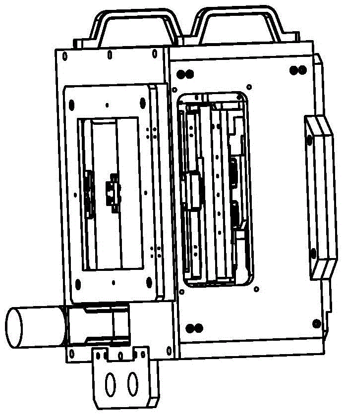
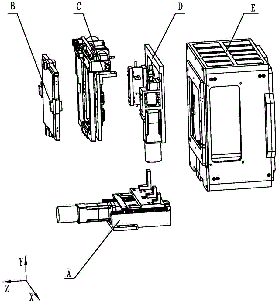
[0023] Specific implementation mode 1. Combination figure 1 Describe this specific embodiment. A three-degree-of-freedom precision adjustment device for a compact back-mounted lens described in this specific embodiment includes a lens clamping module B, an X-direction position adjustment unit C, and a Y-direction position adjustment unit D and Z. To position adjustment unit A and lens case E,

[0024] The lens clamping module B is used to clamp the lens, the lens clamping module B is installed on the X-direction position adjustment unit C, and the X-direction position adjustment unit C is used to drive the lens clamping module B to move in the X direction, The X-direction position adjustment unit C is installed on the Y-direction position adjustment unit D, and the Y-direction position adjustment unit D is used to drive the X-direction position adjustment unit C to move in the Y direction, and the Y-direction position adjustment unit D is installed at the Z-direction position ...

specific Embodiment approach 2

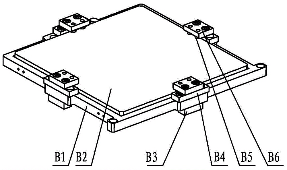
[0026] Specific embodiment two, combine Figure 3-Figure 5 Describe this specific embodiment. The difference between this specific embodiment and the three-degree-of-freedom precision adjustment device for a compact back-mounted lens described in Embodiment 1 is that the lens clamping module B includes a lens support frame B1, Lens B2, lens holding block B3, lens holding block B4, rubber pressing block B5, lens pressing block B6 and elastic washer B7,

[0027] The lens B2 is installed inside the lens support frame B1, and the same side of the four frames of the lens support frame B1 is fixed with a lens pressing block B6, and the lens clamping pad is used between the lens pressing block B6 and the lens support frame B1 B4 is fixed, the bottom of each lens pressing block B6 is fixed with a rubber pressing block B5, and the other side of the three frames of the lens supporting frame B1 is respectively fixed with a lens holding block B3, and each lens holding The top of the bloc...

specific Embodiment approach 3

[0029] Specific embodiment three, combine Figure 6-Figure 7 Describe this specific embodiment. The difference between this specific embodiment and the three-degree-of-freedom precision adjustment device for a compact back-mounted lens described in the second specific embodiment is that the X-direction position adjustment unit C includes a focus lens moving frame C1, X-direction linear motion guide rail C2, X-direction linear motion slider C3, lens holder guide rail C4, X-direction screw rod C5, X-direction connector C6, motion connecting plate C7, X-direction travel trigger C8, X-direction travel switch Support C9, X-direction travel switch C10, Y-direction linear motion guide rail C11, Y-direction linear motion slider C12, Y-direction connector C13, X-direction screw nut C14, X-direction screw bearing seat C15, X-direction bearing seat Block C16, X-direction coupling C17, X-direction drive module support C18, X-direction drive module C19 and Y-direction stroke trigger C20, ...


PUM


Abstract

A three-degree-of-freedom precision adjustment device for a compact back-mounted lens relates to the field of three-degree-of-freedom precision adjustment devices for optical lenses. The adjustment device includes a lens clamping module, an X-direction position adjustment unit, a Y-direction position adjustment unit, a Z-direction position adjustment unit and a lens housing. The lens clamping module is used to clamp the lens, and the lens clamping module is installed on On the X-direction position adjustment unit, the X-direction position adjustment unit is used to drive the lens clamping module to move in the X direction, the X-direction position adjustment unit is installed on the Y-direction position adjustment unit, and the Y-direction position adjustment unit is used for Drive the X-direction position adjustment unit to move in the Y direction, the Y-direction position adjustment unit is installed on the Z-direction position adjustment unit, the Z-direction position adjustment unit is used to drive the Y-direction position adjustment unit to move in the Z direction, and the Z-direction position adjustment unit The adjustment unit is mounted on the lens housing. The invention is suitable for adjusting the position of the lens in the laser fusion target room.

Description

technical field [0001] The invention relates to the field of three-degree-of-freedom precision adjustment devices for optical lenses. Background technique [0002] The limited reserves of non-renewable energy represented by fossil fuels cannot sustain the long-term development of mankind. Nuclear fusion has the advantages of less environmental pollution, sufficient fuel, and large energy release, and is expected to achieve sustainable energy supply. As one of the methods of controlled nuclear fusion, inertial confinement laser fusion has been highly valued by the scientific and technological circles in recent years. [0003] To produce the ultra-high temperature and ultra-high pressure conditions required for fusion, multiple high-energy lasers must be precisely focused on the target sphere in the target chamber. Therefore, the precise adjustment of the spatial position of the focusing lens is one of the key technologies for inertial confinement laser fusion. However, it ...

Claims


Application Information

Patent Timeline
Patent Type & Authority Patents(China)
IPC IPC(8): G02B7/04
CPCG02B7/022G02B7/04
Inventor 白清顺何欣张鹏邵忠喜于福利卢礼华
Owner HARBIN INST OF TECH
Why Eureka
Try Eureka