Method for determining lifting force and resistance moment of spiral wing

A technique for determining the drag torque and its determination method, which is applied in the field of aircraft control and can solve problems such as large amount of calculation, limited use, and difficult mathematical models

Active Publication Date: 2015-04-08
BEIJING INST OF AEROSPACE CONTROL DEVICES
View PDF5 Cites 8 Cited by
  • Summary
  • Abstract
  • Description
  • Claims
  • Application Information

AI Technical Summary

Problems solved by technology

The magnitude of its force is proportional to the rotational speed, and the shape of the spiral wing has a direct impact on its lift, but the shape of the spiral wing is not fixed, so it is very difficult to establish a unified mathematical model
At present, most of the rotorcraft control adopts the method of fuzzy control. This method is simple in modeling, but has a large amount of calculation. In the application of small unmanned aerial vehicles (such as quadrotor aircraft), wireless data transmission must be carried out Human-machine control, which limits the range of motion of the aircraft and also limits its use

Method used


Image

  • Method for determining lifting force and resistance moment of spiral wing
  • Method for determining lifting force and resistance moment of spiral wing
  • Method for determining lifting force and resistance moment of spiral wing

Examples


Embodiment Construction

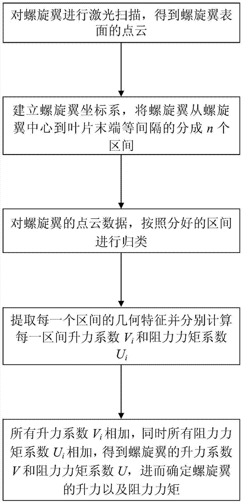
[0048] Such as figure 1 Shown, the present invention provides a kind of determination method of screw wing lift and drag moment, and the steps are as follows:

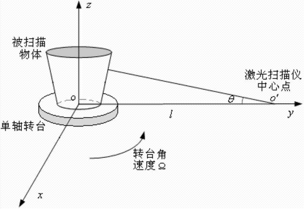
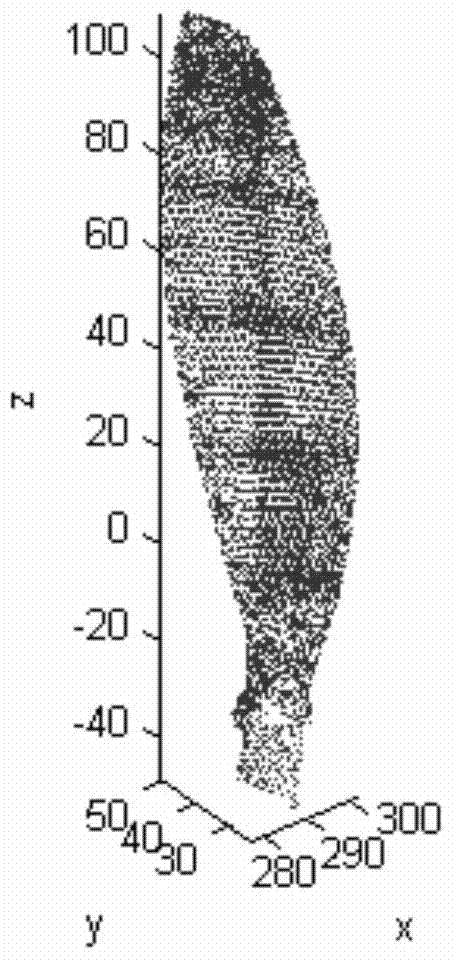
[0049] (1) According to the laser three-dimensional imaging stereo method based on the cooperative target, the laser scanning of the spiral wing is carried out to obtain the point cloud of the surface of the spiral wing, as shown in figure 2 and image 3 shown; figure 2 The laser scanning process is described in , the object to be measured is placed on a constant speed turntable that rotates at an angular velocity of Ω, the coordinate axes and the laser position are shown in the figure, and R is the measured value. image 3 In is a schematic diagram of the point cloud obtained after scanning.

[0050] Specifically:

[0051] (1.1) Put the screw wing on the single-axis turntable, and place one of the blades of the screw wing along the angular velocity direction of the single-axis turntable;

[0052] (1.2) Let the ...


PUM


Abstract

The invention relates to a method for determining lifting force and resistance moment of a spiral wing. According to the method, firstly, a laser three-dimensional imaging method based on a cooperative target is utilized for scanning to obtain three-dimensional point cloud of the spiral wing, and then, the feature of centrosymmetry of the spiral wing is utilized for analyzing one blade. Firstly, the blade is divided into n equal parts, next, the geometric feature of each part is extracted, in addition, the lifting force coefficient and the resistance coefficient are calculated, then, the lifting force coefficients of each part are superimposed, the resistance coefficients are superimposed, and the lifting force coefficient and the resistance coefficient of the spiral wing are obtained. Finally, the lifting force coefficient and the resistance coefficient are substituted into a spiral wing lifting force and angular velocity relational expression deduced according to an air resistance model and a received resistance moment and angular velocity relational expression of the spiral wing, and the lifting force and resistance moment of a spiral wing can be determined. The method has the advantages that the spiral wings in any shapes can be scanned, in addition, the lifting force and angular velocity relationship and the resistance moment and angular velocity relationship of the spiral wing is given, and wide applicability is realized.

Description

technical field [0001] The invention relates to a method for determining lift force and resistance moment of a helical wing, and belongs to the technical field of aircraft control. Background technique [0002] Rotorcraft, such as large helicopters and small quadrotor drones, are a type of aircraft. The rotor is the main propulsion device. In some cases where the geographical environment is complex, the space is small, and a certain area needs to be continuously concerned, the rotorcraft is undoubtedly the most suitable choice. In terms of unmanned aerial vehicles, the rotorcraft can be miniaturized, so that it has the advantages of flexible maneuverability, good concealment, easy operation, flexible configuration, and wider operating range. For example, it can be used for reconnaissance and individual combat in the military; some large-scale monitoring, such as pipeline patrol, farmland disease and pest monitoring, and small rotor drones can complete tasks more efficiently...

Claims


Application Information

Patent Timeline
Patent Type & Authority Applications(China)
IPC IPC(8): G06F19/00
Inventor 魏宗康吕腾赵龙郭子伟
Owner BEIJING INST OF AEROSPACE CONTROL DEVICES
Why Eureka
Try Eureka