
Plasma photonic crystal generating device

A photonic crystal and plasma technology, applied in the direction of plasma, electrical components, etc., can solve the problems of small size of plasma photonic crystal and difficult control of plasma parameter changes

Inactive Publication Date: 2015-04-08
NAT SPACE SCI CENT CAS
View PDF6 Cites 18 Cited by
  • Summary
  • Abstract
  • Description
  • Claims
  • Application Information

AI Technical Summary

Problems solved by technology

[0004] The object of the present invention is to provide a device for generating a plasma photonic crystal, which can produce a structure Large-area plasmonic photonic crystal with convenient constant control

Method used


Image

  • Plasma photonic crystal generating device
  • Plasma photonic crystal generating device
  • Plasma photonic crystal generating device

Examples


Embodiment Construction

[0029] A device for generating a plasmonic photonic crystal according to the present invention will be described in detail below with reference to the drawings and embodiments.

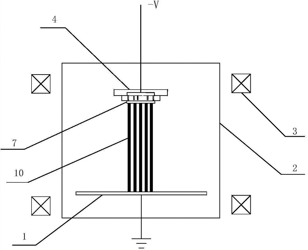
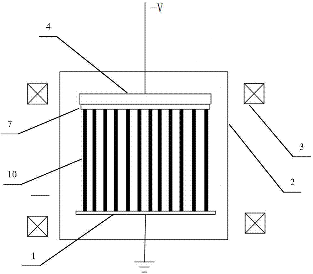
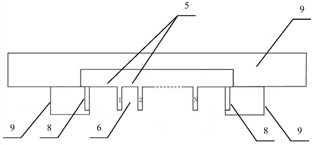
[0030] Such as figure 1 , 2 As shown, a device for generating plasma photonic crystals of the present invention includes: an anode plate 1, a combined hollow cathode 4, a vacuum discharge chamber 2 and a Helmholtz coil set outside the vacuum discharge chamber 2 3. The vacuum discharge chamber 2 is coaxially arranged with the Helmholtz coil 3; the combined hollow cathode 4 is arranged in the vacuum discharge chamber 2 opposite and parallel to the anode plate 1; as image 3 As shown, the combined hollow cathode includes several T-shaped cathode bottom plates 5; the T-shaped cathode bottom plates 5 are arranged in parallel on the same plane, and a concave hole is formed between two adjacent T-shaped cathode bottom plates 5. Slotted cathode 6; as figure 1 , 2 As shown, the bottom of the combined hollo...


PUM


Abstract

The invention provides a plasma photonic crystal generating device. The plasma photonic crystal generating device comprises an anode plate (1), a combined hollow cathode (4), a vacuum discharge cavity (2), and a Helmholtz coil (3) sleeving the vacuum discharge cavity (2). The combined hollow cathode (4) comprises a plurality of T-shaped cathode base plates (5) which are arranged in parallel on the same plane, and groove-shaped cathodes (6) are formed between every two neighboring T-shaped cathode base plates (5); a flat plate (7) provided with a plurality of through holes is arranged under the combined hollow cathode (4) and is parallel to the combined hollow cathode (4); the plurality of through holes are uniformly arranged right under the groove-shaped cathodes (6). According to the plasma photonic crystal generating device, through structural mold regulation of the flat plate, plasma photonic crystals having the same period distribution with the flat plate can be obtained, so that control over the structural constant of the plasma photonic crystals can be achieved.

Description

technical field [0001] The invention relates to the field of plasma application technology, in particular to a device for generating plasma photonic crystals. Background technique [0002] A photonic crystal refers to a structural material whose refractive index changes periodically. At certain frequencies, electromagnetic waves cannot propagate in it, forming a photonic band gap, and the frequency of the forbidden electromagnetic wave will change with the period of the photonic crystal. And change. Plasma photonic crystals are structural materials obtained by periodically arranging plasma and vacuum or other media according to certain rules. Because the plasma itself has the characteristics of "high-pass and low resistance" to electromagnetic waves, and its own parameters and spatial structure are easy to control, therefore, the photonic crystal formed by the plasma has special properties that ordinary photonic crystals do not have. At the same time, this The lattice cons...

Claims


Application Information

Patent Timeline
IPC IPC(8): H05H1/46
Inventor 夏俊明霍文青孙海龙徐跃民孙简
Owner NAT SPACE SCI CENT CAS
Learn More