Display unit and electronic apparatus

A display unit and sub-pixel technology, applied in circuits, electrical components, electrical solid devices, etc., can solve the problems of monochromatic chromaticity changes, brightness balance interference, white or intermediate chromaticity changes, etc., to suppress mixing and improve viewing angles. Characteristics, the effect of optimizing the starting angle of color mixing

Active Publication Date: 2015-04-08
SONY CORP
View PDF9 Cites 16 Cited by
  • Summary
  • Abstract
  • Description
  • Claims
  • Application Information

AI Technical Summary

Problems solved by technology

However, the display unit of the related art has a problem that when the viewing angle characteristic varies depending on the color, the white balance is disturbed so that the chromaticity of white or halftone varies depending on the viewing angle
Therefore, there is a problem that when the space causes a color leak from a color filter adjacent to the space, the luminance balance is disturbed and the chromaticity of a single color changes, causing a color difference (color shift) at a wide viewing angle

Method used


Image

  • Display unit and electronic apparatus
  • Display unit and electronic apparatus
  • Display unit and electronic apparatus

Examples


example 1

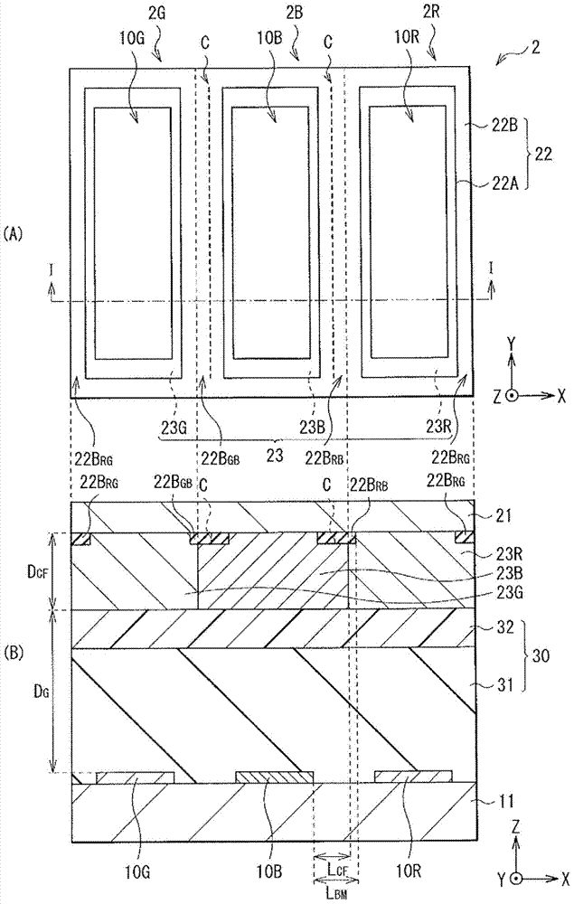
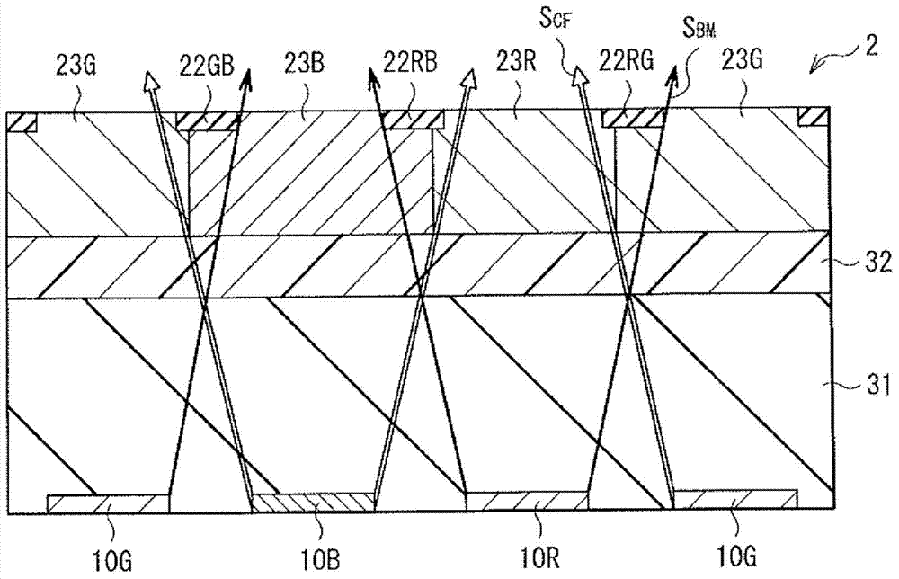
[0155] Figure 20 (A) and (B) illustrate light shielding by the light shielding portion 22B in the related art by a light shielding method that prevents the color light from the blue sub-pixel 2B from being mixed into the color light from the red sub-pixel 2R (compare example) (see Figure 20 (A)) becomes the light shielding performed by the color element 23 according to the embodiment (refer to Figure 20 The improvement in the color mixing initiation angle obtained from (B)). Figure 20 The distance (L CF ), Figure 20 The distance (L BM ), the film thickness from the upper end of the blue light emitting device 10B to the lower end of the resin layer 32 (D G ) and the film thickness of the color element 23 (D CF )as follows:

[0156] L CF : 0.9 microns

[0157] L BM : 1.5 microns

[0158] D. G : 4 microns

[0159] D. CF : 2 microns

[0160] It can be found that when the above values ​​are substituted into the conditional expression, the expression (2) is satis...

example 2

[0163]In Example 2, the basic configuration shown in Example 1 (Experimental Example 1) and the position of the color boundary between the color elements 23 in the sub-pixels 2R, 2G, and 2B, the film thickness, and the backward direction of the light shielding portion 22B Experiments were carried out in Experimental Examples 2 to 8 in which the offset amount was changed from the value in the above basic configuration to the following value. Table 1 provides an overview of the position of the color boundary between the color elements 23, the film thickness of the color elements 23, and the rearward offset of the light shielding portion 22B. Table 2 provides an overview of changes in viewing angles of the red sub-pixel 2R, green sub-pixel 2G, and blue sub-pixel 2B in Experimental Examples 1 to 8. It should be noted that, as used herein, the backward shift amount of the light shielding portion 22B refers to the shift of the center position of the light shielding portion 22 toward...


PUM


Abstract

A display unit includes a light emitting layer including a light emitting device (10R, 10G, 10B); a color filter layer including a color filter (23R, 23G, 23B) corresponding to the light emitting device; and a light blocking layer (22) including a light blocking member (22B) arranged to overlap an end of the color filter, a center position of the light blocking member being offset from the end of the color filter.

Description

technical field [0001] The present invention relates to a display unit that emits light by means of an organic electroluminescence (EL) phenomenon and an electronic device including the display unit. Background technique [0002] In a display unit using a self-luminous device such as an organic EL device, the self-luminous device is provided on one of a pair of substrates, and a light-shielding black matrix is ​​provided on the other substrate. In such a full-color display unit of the related art, colors of light emitted from respective monochrome light emitting devices are mixed to display white or intermediate colors. However, the display unit of the related art has a problem that when viewing angle characteristics vary with colors, white balance is disturbed so that the chromaticity of white or neutral colors varies depending on viewing angles. When the monochromatic light emitted by each light emitting device is mixed with light of other colors emitted by adjacent light...

Claims


Application Information

Patent Timeline
Patent Type & Authority Applications(China)
IPC IPC(8): H01L51/52H01L27/32
CPCH01L27/322H01L51/5265H01L51/5284H10K59/38H10K50/852H10K50/865H10K59/35H10K59/10H10K59/126H10K59/351H10K59/352H10K59/353
Inventor 元山阳介浅木玲生
Owner SONY CORP
Why Eureka
Try Eureka