Automatic edge curling device for steel door panels

A technology of curling device and door panel, which is applied in the direction of feeding device, stripping device, positioning device, etc., can solve the problems of reducing the service life of the equipment, labor, and increasing the cost of the enterprise, so as to save processing costs, ensure the quality of curling, The effect of prolonging the service life

Inactive Publication Date: 2015-04-15
天津华夏防火设备有限公司
View PDF0 Cites 0 Cited by
  • Summary
  • Abstract
  • Description
  • Claims
  • Application Information

AI Technical Summary

Problems solved by technology

[0003] Among them, the feeding platform in the existing equipment is just a simple support platform for supporting the panel to be processed, and there is no limit device for the panel. stage), so that the panel is easy to deviate only under the drive of the roller group, the produced panel is unqualified, and more waste is produced, resulting in waste and increasing the cost of the enterprise
[0004] Only one of the upper and lower pressure rollers in the existing equipment is a rotating wheel. This structure is more laborious when driving the panel to move and curling the panel, which improves the wear rate of the upper and lower pressure rollers and reduces equipment lifespan
[0005] Existing equipment often only relies on the roller group to pull and move the panel. Since the roller group only acts on one side of the panel, the force on the panel is uneven. During the travel of the panel, the panel is easy to deviate, resulting in incomplete and uneven panels.

Method used


Image

  • Automatic edge curling device for steel door panels
  • Automatic edge curling device for steel door panels
  • Automatic edge curling device for steel door panels

Examples


Embodiment Construction

[0018] Below in conjunction with accompanying drawing and specific embodiment the present invention will be described in further detail:

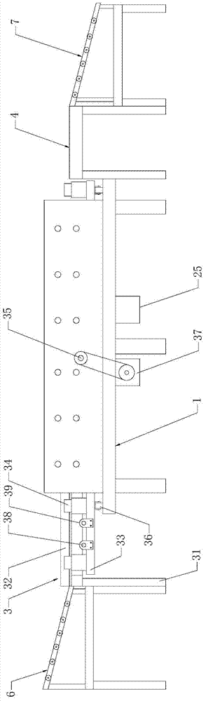
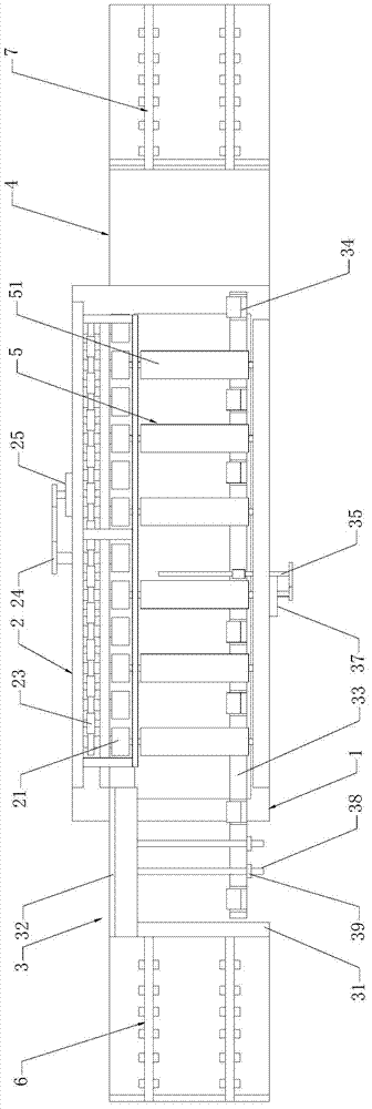
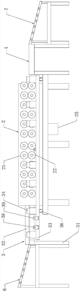
[0019] see Figure 1 to Figure 6 , the present invention includes a frame 1, a roller group 2 installed on one side of the frame 1 and used for one-sided curling of panels, a loading platform 3 installed at one end of the frame 1, and a lower panel installed at the other end of the frame 1. Material platform4.

[0020] The feeding platform 3 includes a frame body 31, a fixed baffle 32, a movable crossbeam 33 and a plurality of movable blocks 34. The fixed baffle 32 is installed on the upper end of the frame body 31 and is close to the side of the roller group 2. The moving The crossbeam 33 is movably installed on the upper end of the frame body 31 by a lead screw 35 and is positioned on the opposite side of the roller group 2. A roller 36 is arranged between the movable crossbeam 33 and the longitudinal bar of the frame 1, and the movable ...


PUM


Abstract

The invention discloses an automatic edge curling device for steel door panels. The automatic edge curling device comprises a frame, a roller group, a loading platform and an unloading platform, wherein the loading platform comprises a rack, a fixed baffle plate, a movable cross beam and a movable stop block; the fixed baffle plate is mounted on the upper end of the rack; the movable stop block is mounted on the movable cross beam; a lead screw is rotated to adjust the space between the fixed baffle plate and the movable cross beam; gears are coaxially mounted on all the upper and lower compression rollers in the roller group and every two gears are engaged with each other; transmission gears are arranged between the coaxial gears of a plurality of upper compression rollers, respectively; a middle roller group for driving a panel to move and guaranteeing the flatness of the panel in the edge curling moving process is arranged above the frame; gaps are formed between the upper and lower middle rollers of the middle roller group; each lower middle roller is coaxially mounted with the corresponding lower compression roller. According to the automatic edge curling device for the steel door panels, the wear rate of the upper and lower compression rollers is reduced so that the stress on the panels can be even, the processing is smooth, the edge curling quality of the panels is guaranteed and the processing cost of an enterprise is saved.

Description

technical field [0001] The invention relates to a steel door panel processing equipment, in particular to an automatic curling device for a steel door panel. Background technique [0002] The existing steel door panel crimping device is generally composed of a frame, a roller group for crimping the panel, a loading platform and an unloading platform. Gradually hem one side of the panel to shape. [0003] Among them, the feeding platform in the existing equipment is just a simple support platform for supporting the panel to be processed, and there is no limit device for the panel. stage), so that the panel is easy to deviate only under the drive of the roller group, the produced panel is unqualified, and more waste is produced, resulting in waste and increasing the cost of the enterprise. [0004] Only one of the upper and lower pressure rollers in the existing equipment is a rotating wheel. This structure is more laborious when driving the panel to move and curling the pan...

Claims


Application Information

Patent Timeline
Patent Type & Authority Applications(China)
IPC IPC(8): B21D19/12B21D43/09B21D45/00
Inventor 王玉军
Owner 天津华夏防火设备有限公司
Why Eureka
Try Eureka