Protection type four-rail support assembly for horizontal coarse framing machine

A technology of supporting components and rough frame machines, which is applied in the direction of maintenance and safety accessories, metal processing machinery parts, large fixed members, etc., can solve the problems of not being able to process heavy workpieces, increasing the manufacturing cost of the protective cover, and difficult expansion and contraction of the protective cover. Achieve the effect of increasing the smoothness of movement, light overall weight and reducing size

Inactive Publication Date: 2015-04-15
昆山华都精工精密机械股份有限公司
View PDF8 Cites 4 Cited by
  • Summary
  • Abstract
  • Description
  • Claims
  • Application Information

AI Technical Summary

Problems solved by technology

The guide rails used for the table feed of this kind of milling machine are generally linear guide rails. Although the linear guide rails have a faster feed speed, their pressure bearing capacity is not strong and their service life is short, so they cannot be applied to processing heavy workpieces.
[0004] In addition, most of the protective covers for protecting the guide rails currently use integral retractable protective covers. When the size of the workbench covered by this type of protective cover is large, the structure of the protective cover needs to be large enough to move the work. The guide rails on the platform are all covered, which increases the manufacturing cost of the protective cover, and during the expansion and contraction process of the protective cover, due to the large volume, it will be difficult to expand and contract the protective cover, and some positions of the protective cover will appear during use. Damaged, the entire protective cover needs to be replaced, which also increases the replacement cost

Method used


Image

  • Protection type four-rail support assembly for horizontal coarse framing machine
  • Protection type four-rail support assembly for horizontal coarse framing machine
  • Protection type four-rail support assembly for horizontal coarse framing machine

Examples


Embodiment Construction

[0038] The technical solutions of the present invention will be further described below in conjunction with the accompanying drawings and through specific implementation methods.

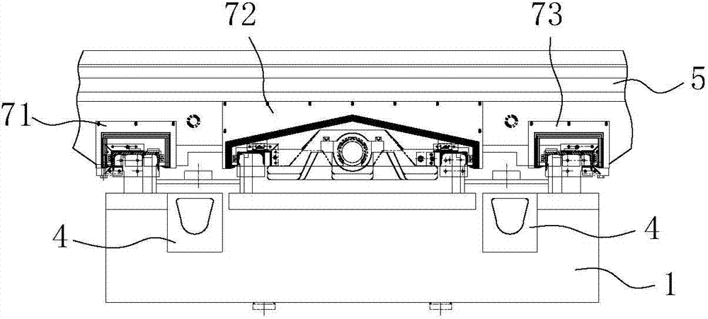
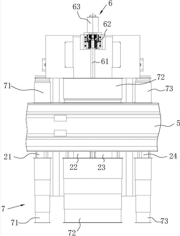
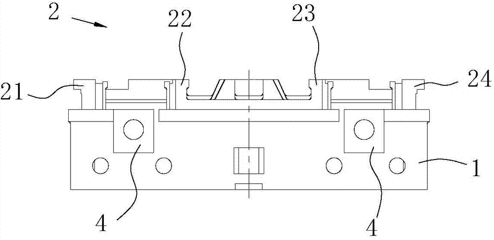
[0039] like Figures 1 to 4 As shown, the protective four-rail support assembly for a horizontal rough frame machine in this embodiment includes a base 1, on which a driving platform 5 is slidably arranged, and the driving platform 5 is placed on the base 1 along the length direction of the base 1 through the driving mechanism 6. move.

[0040] Four guide rails 2 parallel to each other are fixedly arranged on the base 1 along its length direction, which are the first guide rail 21, the second guide rail 22, the third guide rail 23 and the fourth guide rail 24 arranged in sequence, and the guide rails 2 and the base 1 are integrally cast. , between the second guide rail 22 and the third guide rail 23, the receiving groove 3 opened along the length direction of the base 1, between the first guide rai...


PUM


Abstract

The invention discloses a protection type four-rail support assembly for a horizontal coarse framing machine. The protection type four-rail support assembly includes a pedestal and driving platform arranged thereon in a sliding manner, wherein four guide rails parallel to one another are arranged on the pedestal; guide grooves are arranged on one side, close to the pedestal, of the driving platform corresponding to the guide rails; and the guide rails and the pedestal are integrally molded by casting; a protective cover assembly for preventing scrap iron from entering into the guide rails is arranged on each of two sides of the driving platform, each protective cover assembly includes three protective covers, the guide rails on two sides are respectively covered by one protective cover, the two guide rails in the middle are covered by one protective cover, and the three protective covers are all retractable protective covers. Through arranging the four guide rails parallel to one another on the pedestal, the movement stability of the driving platform can be increased; the guide rails and the pedestal are integrally molded by casting, so that the loading capacity of the guide rails can be increased, and the driving accuracy of the guide rail is ensured; with the usage of the protective covers of separating structure, the sizes of the protective covers can be reduced, and the maintenance cost is reduced.

Description

technical field [0001] The invention relates to the technical field of processing machine tools, in particular to a protective four-rail support assembly for a horizontal rough-frame machine. Background technique [0002] Milling machine is one of the commonly used equipment for rough frame processing in the machining industry. It mainly uses milling cutters to process various surfaces on workpieces. The main movement is the rotation of the milling cutter, and the movement of the workpiece or milling cutter is the feed movement. It can process Flat surfaces, grooves, and various curved surfaces can also be processed, and are widely used in machinery manufacturing and repair departments. [0003] Its general structure of the existing milling machine is a base, the base is provided with a fixed column, the fixed column has an extension arm, the main shaft and the vertical cutter are installed on the extension wall, and the cutter is fixed with the main shaft. Here, the tool w...

Claims


Application Information

Patent Timeline
Patent Type & Authority Applications(China)
IPC IPC(8): B23Q1/01B23Q11/08B23Q1/25
CPCB23Q1/015B23Q1/017B23Q11/08
Inventor 向彬
Owner 昆山华都精工精密机械股份有限公司
Why Eureka
Try Eureka