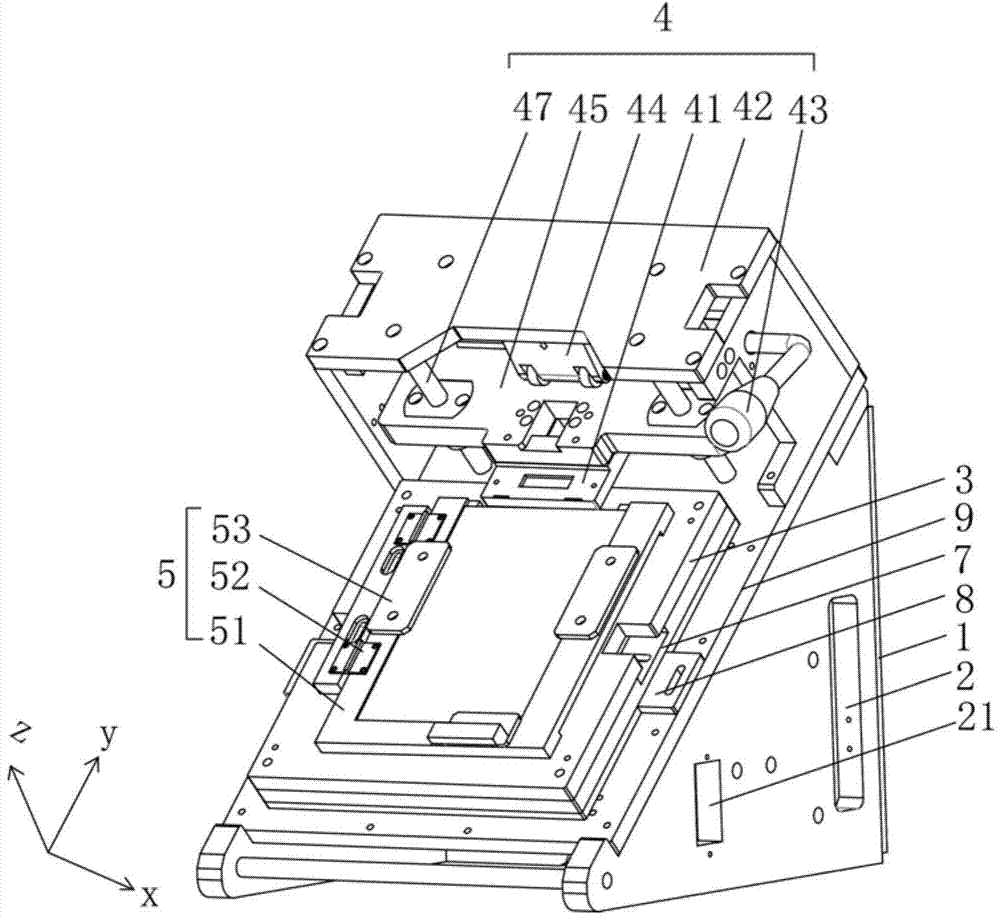
Testing fixture

A test fixture and test signal technology, applied in nonlinear optics, instruments, optics, etc., can solve problems such as unfavorable rapid production, cluttered equipment placement, increased replacement frequency and missed detection rate, etc., to achieve convenient management and maintenance, Conducive to operation and production, the effect of the best inspection angle

Active Publication Date: 2015-04-15
BOE TECH GRP CO LTD +1
View PDF5 Cites 21 Cited by
  • Summary
  • Abstract
  • Description
  • Claims
  • Application Information

AI Technical Summary

Problems solved by technology

[0003] There are many defects in the application of existing test fixtures: first, the fixture itself and the signal source are set separately, and the two must be connected through an external cable when in use
In this way, the overall equipment placement will be messy at the operation site, which is not conducive to workshop operation and unified management; moreover, under normal circumstances, the fixture is only operated on the horizontal plane during the signal test, which cannot provide a better detection angle of view. It is conducive to rapid production; secondly, the polarizer on the fixture is usually directly attached to the surface of the carrier with an acrylic plate, which not only leads to low light transmittance of the polarizer, but also easily causes serious scratches, which greatly increases the cost of replacement. Frequency and missed detection rate; at the same time, the fixture carrier and the backlight are usually integrated, that is, the backlight is directly fixed in the backlight groove behind the carrier, which is not convenient for cleaning and maintenance of the backlight; in addition, the fixture on the pressure head There is no avoidance at the installation end of the probe, which will cause damage to non-test points when the indenter is reciprocating, causing unnecessary damage

Method used


Image

  • Testing fixture
  • Testing fixture
  • Testing fixture

Examples


Embodiment Construction

[0037] The embodiments of the present invention will be described in further detail below in conjunction with the drawings and examples. The following examples are used to illustrate the present invention, but cannot be used to limit the scope of the present invention.

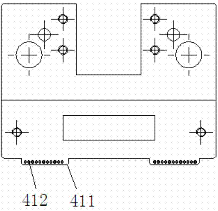
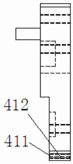
[0038] In the description of the present invention, unless otherwise specified, "plurality" means two or more; the terms "upper", "lower", "left", "right", "inner", "outer" , "Front", "Back", "Head", "Tail", etc. indicate the orientation or positional relationship based on the orientation or positional relationship shown in the drawings, and are only for the convenience of describing the present invention and simplifying the description, not It indicates or implies that the pointed device or element must have a specific orientation, be constructed and operated in a specific orientation, and therefore cannot be understood as a limitation of the present invention. In addition, the terms "first", "second", "third",...


PUM


Abstract

The invention relates to the technical field of display, in particular to a testing fixture. The testing fixture comprises a base, a signal source, an operating microscope stage and a crimp connection mechanism, wherein an inclined plane for bearing the operating microscope stage and the crimp connection mechanism is arranged on the base; the signal source is positioned on the base; the crimp connection mechanism is used for applying testing signals emitted by the signal source to a product to be tested; the operating microscope stage performs light-on testing on the product to be tested. The testing fixture can effectively accomplish light-on testing on the product to be tested, is convenient for management and maintenance through integrated design of the base, the signal source, the operating microscope stage and the crimp connection mechanism, moreover, the testing fixture has better detecting visual angle as the inclined plane for bearing the operating microscope stage and the crimp connection mechanism is further arranged on the base, thereby being beneficial to operation and production.

Description

Technical field [0001] The present invention relates to the field of display technology, in particular to a test fixture, and more specifically, a test fixture that has a better detection angle and is convenient for installation and maintenance. Background technique [0002] At present, LCD (English name is Liquid Crystal Display, Chinese name is Liquid Crystal Display) due to its technical advantages, has been widely used in production and life. In the LCD production process, it is often necessary to use an auxiliary tool with a test signal to complete the LCD test. The auxiliary tool can provide a signal connection between the LCD and the test signal, and connect the test point of the signal source to the corresponding test point of the product to be tested, and complete the test of the product to be tested in the lighted state. [0003] The existing test fixture has many defects in application: First, the fixture itself and the signal source are set separately, and the two must...

Claims


Application Information

Patent Timeline
Patent Type & Authority Applications(China)
IPC IPC(8): G02F1/13
CPCG02F1/1309
Inventor 薛李伟李剑王德超
Owner BOE TECH GRP CO LTD
Why Eureka
Try Eureka