Touch panel

A technology of touch panel and cover plate, applied in the direction of electronic equipment, lamination, application, etc., to achieve the effect of reducing damage, low production cost, and reducing erosion

Active Publication Date: 2015-04-15
TPK TOUCH SOLUTIONS (XIAMEN) INC
View PDF5 Cites 9 Cited by
  • Summary
  • Abstract
  • Description
  • Claims
  • Application Information

AI Technical Summary

Problems solved by technology

[0003] However, with the ever-increasing demand for lightness, thinness and low cost in the manufacturing process of the touch panel, the current existing touch panel structure and manufacturing process need to be further improved.

Method used


Image

  • Touch panel
  • Touch panel
  • Touch panel

Examples


Embodiment Construction

[0040] The present invention will be further described in detail below in conjunction with the accompanying drawings and specific embodiments.

[0041] The disclosure of the present invention may use repeated element symbols in different embodiments, which does not mean that there is a relationship between different embodiments or drawings. In addition, an element formed "on" or "under" another element may include an embodiment in which the two elements are in direct contact, or an embodiment in which other additional elements are interposed between the two elements. Various elements may be shown in arbitrarily different scales for clarity and simplicity of illustration.

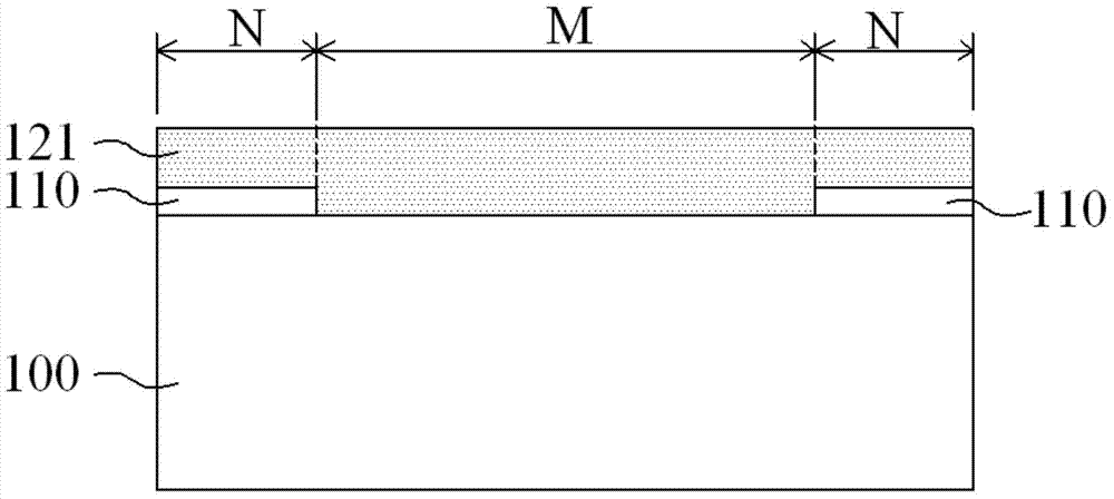
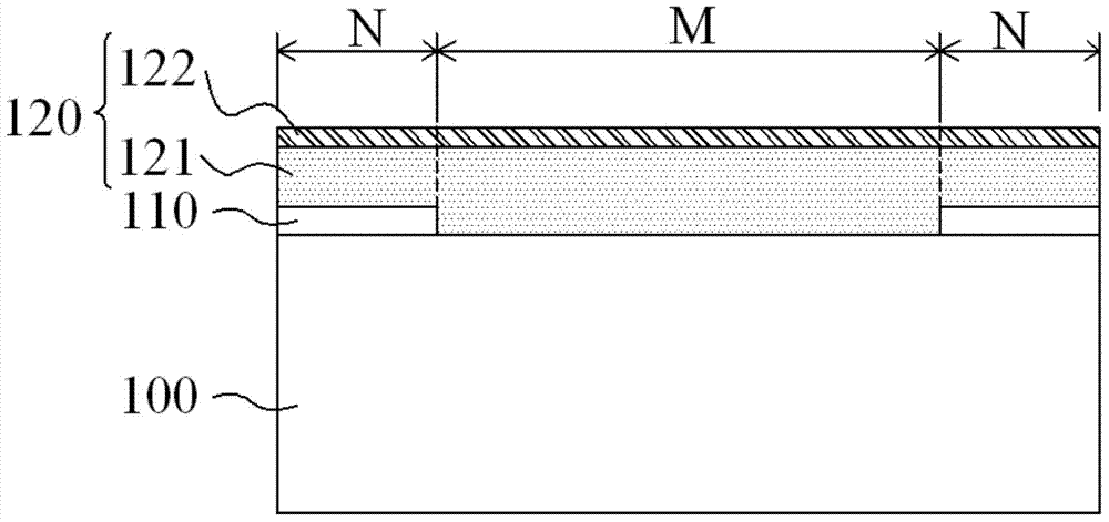
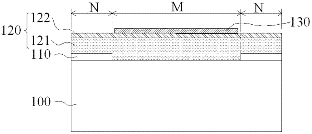
[0042] Figure 1A ~ Figure 1H It is a flowchart of a manufacturing method of a touch panel according to an embodiment of the present invention. in Figure 1H It is also a schematic structural diagram of the touch panel formed by the manufacturing method according to an embodiment of the present invention. ...


PUM


Abstract

A touch panel is formed by firstly forming a film layer on a first plate, and next, sequentially forming a buffer layer on the film layer, forming a sensing layer on the buffer layer, forming a second plate on the sensing layer. After the foregoing formation procedures, the first plate is removed from the film layer. Next, a cover is attached to the film layer. In this way, the film layer is located between the cover and the buffer layer. Finally, the second plate is removed from the sensing layer, so as to form a touch panel with the features of light weight, thin thickness and low costs.

Description

technical field [0001] The present invention relates to the field of touch technology, in particular to a touch panel. Background technique [0002] In today's consumer electronics market, touch panels have been used in various electronic products, such as smart phones, mobile phones, tablet computers and notebook computers. Since the user can directly operate and issue instructions through the objects displayed on the screen, the touch panel provides a humanized operation interface between the user and the electronic product. [0003] However, with the ever-increasing demands on the lightness and thinness of the structure of the touch panel and the low cost of the manufacturing process, the current existing touch panel structure and manufacturing process need to be further improved. Contents of the invention [0004] Embodiments of the present invention provide a touch panel to meet the requirements of a lighter and thinner structure and lower cost in the manufacturing p...

Claims


Application Information

Patent Timeline
Patent Type & Authority Applications(China)
IPC IPC(8): G06F3/041
CPCY10T428/31931Y10T428/31935H03K17/9618B32B43/006B32B2037/243B32B38/0008G06F3/047Y10T428/31507B32B37/24B32B38/0004B32B37/025B32B2038/0076B32B2310/0831Y10T428/31721Y10T428/31544Y10T428/31938G06F1/1692Y10T428/31786B32B2307/202B32B2457/208B32B38/0036B32B2305/38B32B33/00G06F3/041G06F3/0412G06F2203/04103G06F2203/04112G02F1/13338G06F2203/04107G06F2203/04111Y10T428/24942Y10T428/265
Inventor 林清山吴春彦纪连杰方芳
Owner TPK TOUCH SOLUTIONS (XIAMEN) INC
Why Eureka
Try Eureka