Method and system for configuring measurement reference signal power control parameters in a time division duplex system

A technology for power control parameters and measuring reference signals, applied in the field of communication

Active Publication Date: 2020-08-04
ZTE CORP
View PDF8 Cites 0 Cited by
  • Summary
  • Abstract
  • Description
  • Claims
  • Application Information

AI Technical Summary

Problems solved by technology

[0041] The invention discloses a measurement reference signal power control parameter configuration method and system in a time division duplex system, which can better solve the problem of using multiple sets of power control parameters to send SRS signals

Method used


Image

  • Method and system for configuring measurement reference signal power control parameters in a time division duplex system
  • Method and system for configuring measurement reference signal power control parameters in a time division duplex system
  • Method and system for configuring measurement reference signal power control parameters in a time division duplex system

Examples


Embodiment 1

[0195] A power control parameter defined by P O_PUSCH,c , α c , f c composition. There are two power control parameters, which are power control parameter 1: 1 O_PUSCH,c , α c 1 , f c 1 > and power control parameter 2: 2 O_PUSCH,c , α c 2 , f c 2 >.

[0196] Note: P O_PUSCH,c by P O_NOMINAL_PUSCH,c and P O_UE_PUSCH,c It consists of two parts. Therefore P 1 O_PUSCH,c with P 2 O_PUSCH,c can be P O_NOMINAL_P different, or P O_UE_PUS different, or P O_NOMINAL_P and P O_UE_PUSCH,c all different.

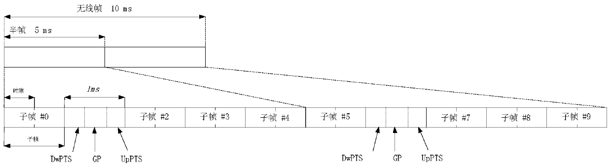
[0197] The SRS resource refers to: a time domain location and / or a frequency domain location. Using different power control parameters for different SRS resources refers to using different power control parameters for different time domain positions and / or frequency domain positions. The SRS resource is in the UpPTS, and there are 2 symbols in an UpPTS for SRS (2ms period) and the SRS resource is used for Trigger type0 SRS.

[0198] Figure 5 It shows that when...

Embodiment 2

[0201] A power control parameter is defined by α c , f c composition. There are two power control parameters, which are power control parameter 1: c 1 , f c 1 > and power control parameter 2: c 2 , f c 2 >.

[0202] The SRS resource refers to: a time domain location and / or a frequency domain location. Using different power control parameters for different SRS resources refers to using different power control parameters for different time domain positions and / or frequency domain positions.

[0203] Let the Trigger type0 SRS be sent in subframes 2 and 7.

[0204] Figure 7 Shows the situation of using power control parameters 1 and 2 alternately in each frequency hopping period when the frequency hopping position is 3: the power control parameters used by the terminal at the same frequency domain position between adjacent frequency hopping periods different. Each time domain position in the same frequency hopping period uses the same power control parameter.

Embodiment 3

[0206] A power control parameter defined by P O_PUSCH,c , α c composition. There are two power control parameters, which are power control parameter 1: 1 O_PUSCH,c , α c 1 > and power control parameter 2: 2 O_PUSCH,c , α c 2 >.

[0207] Note: P O_PUSCH,c by P O_NOMINAL_PUSCH,c and P O_UE_PUSCH,c It consists of two parts. Therefore P 1 O_PUSCH,c with P 2 O_PUSCH,c can be P O_NOMINAL_P different, or P O_UE_PUS different, or P O_NOMINAL_PUSCH,c and P O_UE_PUSCH,c all different.

[0208] Configure two SRS processes. The time domain positions of the two SRS processes are different (configured independently through the period and subframe offset), and the positions in the frequency domain are different (independently configured through the frequency domain start PRB and or frequency hopping parameters).

[0209] like Figure 8 As shown, for Trigger type0 SRS, the period of process 1 is 5ms, and the subframe offset is 0; the period of process 2 is 5ms, and the s...


PUM


Abstract

The invention discloses a measurement reference signal power control parameter configuration method in a time division duplex system, which is applied in a terminal and a system, and includes: the terminal determines the power control parameter of the measurement reference signal SRS resource, and determines the measurement reference signal according to the power control parameter The transmission power of the signal; the terminal sends the measurement reference signal SRS according to the determined transmission power of the measurement reference signal SRS, and the base station determines the power control parameters used by the terminal on the SRS resource; the base station receives the SRS signal according to the power control parameters. The invention also discloses a measurement reference signal power control parameter configuration system in the time division duplex system, which corresponds to the above method. The invention has good flexibility and can improve the utilization rate of uplink resource in TDD mode.

Description

technical field [0001] The invention relates to the communication field, in particular to a method for determining the power control parameters of a measurement reference signal in a time division duplex system. Background technique [0002] figure 1 It is a schematic diagram of the frame structure of the Time Division Duplex (TDD) mode of the LTE system (note: this frame structure is also called the second type of frame structure, that is, frame structure type2). In this frame structure, a 10ms (307200Ts, 1ms=30720Ts) wireless frame is divided into two half-frames, and the length of each half-frame is 5ms (153600Ts). Each half frame contains 5 subframes with a length of 1 ms. The function of each subframe is shown in Table 1, where D represents the downlink subframe used to transmit downlink signals, and U represents the uplink subframe used to transmit uplink signals ( Or called a common uplink subframe), and S represents a special subframe. In addition, an uplink or do...

Claims


Application Information

Patent Timeline
Patent Type & Authority Patents(China)
IPC IPC(8): H04L1/00H04W52/54
CPCH04W52/325H04W52/54H04W52/42H04L1/0001H04L5/22H04B1/7143H04L5/1469H04W52/146
Inventor 郝鹏李卫敏
Owner ZTE CORP
Why Eureka
Try Eureka