Automatic lamp holder riveting pressure device

A riveting needle and strip technology, applied in the field of lamp head riveting and pressing device and riveting mechanism, can solve the problems of lamp head displacement, affecting lamp head, driving lamp head to deviate, etc., and achieve the effect of simplifying structure, uniform distribution, and avoiding lamp head deviation.

Inactive Publication Date: 2015-04-22
MAANSHAN LIANBANG INTELLIGENT EQUIP
View PDF5 Cites 0 Cited by
  • Summary
  • Abstract
  • Description
  • Claims
  • Application Information

AI Technical Summary

Problems solved by technology

[0010] Aiming at the problems in the prior art that the riveting needle may drive the lamp head to deviate or give it a certain pulling force when the riveting device is opened, the stability of the lamp head will be affected when the riveting device is opened, and the lamp head will be displaced when the riveting needle is separated from the lamp head. The invention provides an automatic lamp head riveting device, which can ensure that the lamp head is at a consistent height when the riveting needle is riveting, and provide a certain holding force for the lamp head, so that the depth of the riveting point produced by the riveting needle is consistent and the distribution is even ; At the same time, it makes the rivet needle stable when it is opened, and avoids the rivet needle from driving the lamp head to shift

Method used


Image

  • Automatic lamp holder riveting pressure device
  • Automatic lamp holder riveting pressure device

Examples


Embodiment 1

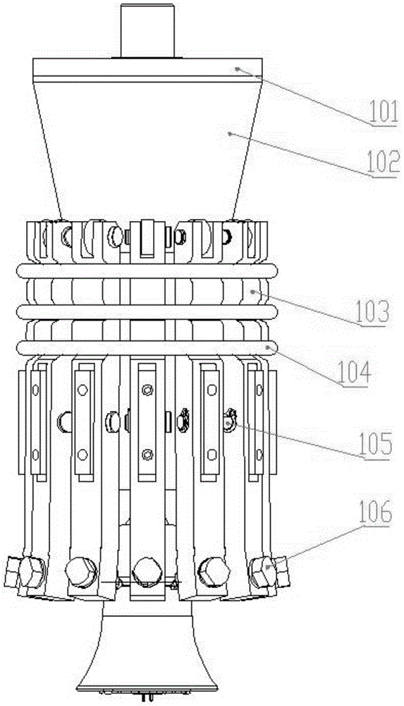
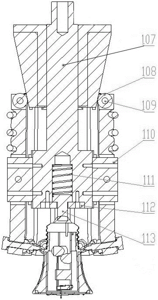
[0029] Such as figure 1 and figure 2 As shown, the pressure riveting device consists of a polyoxymethylene sleeve 101, a conical table 102, a strip lever 103, a small extension spring 104, a round pin 105, a riveting needle 106, a fixed shaft seat 107, a roller 108, a roller shaft 109, and a small square 110, small stage clip 111, stuffy cover 112, top post 113 form.

[0030] The polyoxymethylene sleeve 101 is threadedly connected with the conical table 102. The polyoxymethylene sleeve 101 is circular and is placed on the upper part of the fixed shaft seat 107, and can slide up and down in its shaft. The polyoxymethylene sleeve 101 is made of polyoxymethylene material. The polymeric material is a lightweight material with a density of 1.4g / cm 3 Left and right, it has high hardness, wear resistance, and is easy to process. When the riveting device and the cylinder work together, the polyoxymethylene sleeve 101 can be processed into a form suitable for connecting with the cyl...


PUM

PropertyMeasurementUnit
densityaaaaaaaaaa

Abstract

The invention discloses an automatic lamp holder riveting pressure device, belongs to the field of mechanical machining equipment, and relates to a riveting mechanism. The automatic lamp holder riveting pressure device comprises a polyformaldehyde sleeve, a conical table, long-bar-shaped levers, a tension spring, round pins, riveting pins, a fixing shaft seat and small blocks, wherein the polyformaldehyde sleeve is fixedly connected with the conical table, the upper end of the fixing shaft seat is sleeved with the polyformaldehyde sleeve, the small blocks are fixedly arranged on the fixing shaft seat, each round pin is formed in the middle of corresponding small block, each corresponding long-bar-shaped lever is hanged on corresponding round pin, the lower end of each long-bar-shaped lever is fixedly provided with the corresponding riveting pin, and the upper end of each long-bar-shaped lever is wrapped and sleeved with the small extension spring. The automatic lamp holder riveting pressure device can provide a certain holding force for a lamp holder to make the depths of riveting points have no difference and make the riveting points be distributed uniformly during riveting pressure of the riveting pins; meanwhile the riveting pins can be stable when the riveting pin riveting pressure is turned on, and excursion of the lamp holder driven by the riveting pins is avoided.

Description

technical field [0001] The invention belongs to the field of mechanical processing equipment, and relates to a riveting mechanism, in particular to a lamp cap riveting device. Background technique [0002] Under the economic model dominated by the market economy, in order to adapt to the rapidly changing market requirements, new requirements are put forward for assembly automation. For automated high-speed mechanical assembly, it is necessary to conduct in-depth research on precision assembly technology to adapt to the challenges brought by the development of modern precision machinery to assembly technology. At the same time, it can also greatly increase the product yield and productivity, reduce the production cost of enterprises, and improve the competitiveness of enterprises, which is of great significance to the development of enterprises and industries. [0003] Riveting and welding are two well-known methods in the industry to connect multiple panels. Among them, riv...

Claims


Application Information

Patent Timeline
Patent Type & Authority Applications(China)
IPC IPC(8): B21D39/00
CPCB21D39/00
Inventor 苏山山倪明姚路路
Owner MAANSHAN LIANBANG INTELLIGENT EQUIP
Why Eureka
Try Eureka