Rail type rope traction aerial passenger device

An overhead passenger device and rope traction technology, which is applied in cable railways, transportation and packaging, motor vehicles, etc., can solve the problems of poor stability, high cost, and many consumables, and achieve good stability, simple structure and high safety. Effect

Active Publication Date: 2015-04-22
湘潭恒欣实业股份有限公司
View PDF6 Cites 15 Cited by
  • Summary
  • Abstract
  • Description
  • Claims
  • Application Information

AI Technical Summary

Problems solved by technology

[0002] Aerial passenger devices are common or necessary passenger transport equipment in underground mines. Traditional aerial passenger devices generally use traction wire ropes to carry the weight of passengers. As a result, the traction wire ropes must simultaneously perform the functions of traction and load-bearing, which may easily lead to fall. There are many safety hazards such as ropes and flying cars, and there are many defects such as poor stability, strong vibration, and uncomfortable riding.
At present, there are mainly two types of rail-type overhead passenger devices. One is to hang the traction wire rope under the track through a dense rail wheel device. The ferrule on the device runs, so this method has a lot of consumables, high cost and difficult to guarantee the installation accuracy. If the rail wheel device slips, it will easily cause the traction wire rope to hang the rope at the driving wheel or tail wheel; The bearing slides are installed at intervals on the track, and the chair chain links are set on the load slides. The traction wire rope passes through the arc-shaped protrusion of the lift chain rings, and two limit positions with a fixed distance between the rail and the wire rope are set in a tangential arrangement. The arc-shaped protrusion of the wheel is located between the two limit wheels arranged tan

Method used


Image

  • Rail type rope traction aerial passenger device
  • Rail type rope traction aerial passenger device
  • Rail type rope traction aerial passenger device

Examples


Embodiment Construction

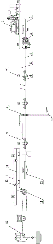
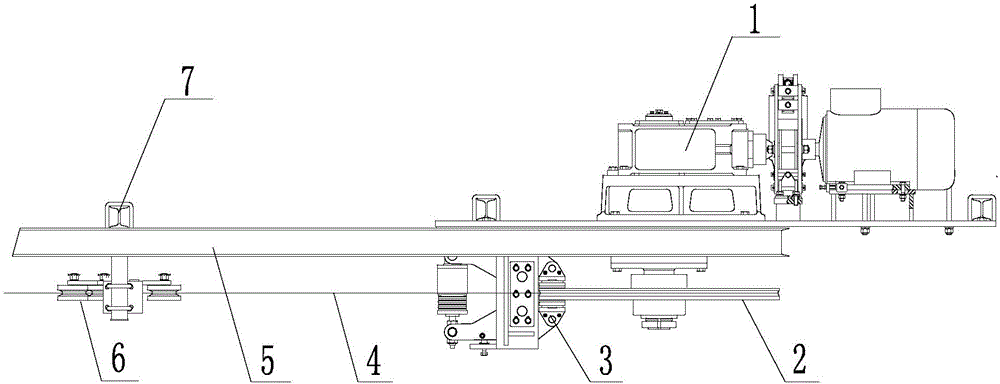
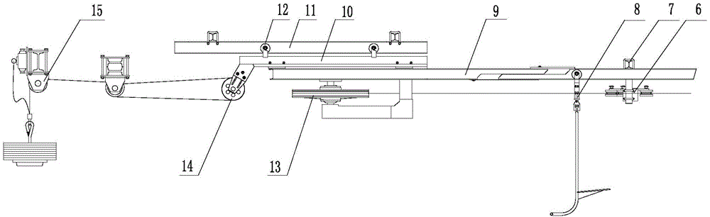
[0029] Such as figure 1 , figure 2 , image 3 , Figure 4 , Figure 5 , Figure 6 , Figure 7 , Figure 8 , Figure 9 , Figure 10 , Figure 11 , Figure 12 , Figure 13 , Figure 14 As shown, a track-type rope traction overhead passenger device, the track-type rope traction overhead passenger device uses a beam 7 as a mounting bracket, and a track 5 parallel to the traction wire rope 4 is installed above the traction wire rope 4. The steel wire rope 4 pulls the passenger device 8 to run on the track 5, the middle section of the traction steel wire rope 4 is stabilized and guided by the supporting pressure rope wheel device 6, and the tail wheel 13 is installed on the tensioning device; the supporting pressure rope wheel device 6, It includes a bracket 17, on which a set of relative pressure sheave assemblies are installed, and the pressure sheave assembly includes two staggered relative rotating swing arms 18, and the rotating swing arms 18 are mounted on the bra...


PUM


Abstract

The invention discloses a rail type rope traction aerial passenger device. A rail which is parallel to a traction steel wire rope is arranged above the traction steel wire rope; the traction steel wire rope is used for pulling a passenger device to run on the rail; the middle section of the traction steel wire rope is stabilized and guided by a rope pressing wheel supporting device; and a tail wheel is mounted on a tensioning device. The rail type rope traction aerial passenger device has the following technical effects: 1. the middle section of the traction steel wire rope is clamped into the rope pressing wheel supporting device so that the rail type rope traction aerial passenger device can change the slope and make a turn, and the passing of a rope clip is not influenced; the structure is simple, few consumable materials are used, the cost is low and the safety is high; 2. the vertical rope clip is adopted, can effectively run while bearing a passenger, also can guarantee that the passenger distance can be randomly adjusted, and can conveniently pass through the rope pressing wheel supporting device, a driving wheel and the tail wheel; the vertical state can be automatically adjusted at uphill and downhill parts and the device is comfort to take; and 3. the retractable rail is arranged in the tensioning device so that the traction steel wire rope and the rail are tensioned simultaneously and the stability is good.

Description

technical field [0001] The invention relates to an overhead passenger equipment, in particular to a rail-type overhead passenger device. Background technique [0002] Aerial passenger devices are common or necessary passenger transport equipment in underground mines. Traditional aerial passenger devices generally use traction wire ropes to carry the weight of passengers. As a result, the traction wire ropes must simultaneously perform the functions of traction and load-bearing, which may easily lead to fall. There are many safety hazards such as ropes and flying cars, and there are many defects such as poor stability, strong vibration, and uncomfortable riding. At present, there are mainly two types of rail-type overhead passenger devices. One is to hang the traction wire rope under the track through a dense rail wheel device. The ferrule on the device runs, so this method has a lot of consumables, high cost and difficult to guarantee the installation accuracy. If the rail ...

Claims


Application Information

Patent Timeline
IPC IPC(8): B61B7/00B61B12/02
CPCB61B7/00B61B12/028
Inventor 肖公平肖连平彭乐
Owner 湘潭恒欣实业股份有限公司
Why Eureka
Try Eureka