Power-losing trigger device

A triggering device, electromagnetic technology, applied in the direction of the hoisting device, can solve the problems of the brake not working, high power consumption, opening failure, etc., to achieve the effect of the energy storage impact structure and the reset structure is simple, the current is reduced, and the service life is improved.

Active Publication Date: 2015-04-22
HANGZHOU HUNING ELEVATOR PARTS CO LTD
View PDF8 Cites 11 Cited by
  • Summary
  • Abstract
  • Description
  • Claims
  • Application Information

AI Technical Summary

Problems solved by technology

[0002] At present, the lock hook of the steel wire rope brake for elevators is triggered by the electric trigger method, and the electric trigger control method has the absence of external power supply, insufficient backup power supply, circuit and equipment failure, and the trigger device cannot trigger the switch of the brake (lock hook ) institutions, resulting in a high degree of security risk
Specifically, the electric trigger method has a long vertical and horizontal safety chain, and the vertical safety chain from the power supply, control logic unit, electromagnet, backup power supply to the trigger device is relatively long, and there are many fault detection and monitoring links in the horizontal electric triggering process. It is difficult to achieve fault-free monitoring and feedback. A fault in one of the links will cause a fatal risk of failure of the switch (locking) mechanism, making the brake unable to operate. slow, high power consumption

Method used


Image

  • Power-losing trigger device
  • Power-losing trigger device
  • Power-losing trigger device

Examples


Embodiment 1

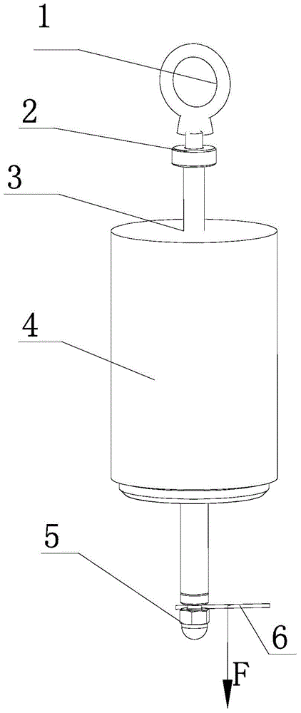
[0049] see Figure 5-6 , the frame 102 is in the shape of a square frame, and its rear side is fixedly connected to the rear plate 118 to form a fixed frame. The left and right sides of the frame 102 are respectively provided with holes, and the upper and lower sides are respectively provided with holes, and the lower holes are the lower guide holes 103 . The corresponding holes on the upper and lower sides of the frame 102 are adapted to the shape of the impact rod 3 , and the upper and lower holes vertically penetrate the impact rod 3 , and the upper and lower holes are used for guiding and installing the impact rod 3 . The upper section of the impact rod 3 is in the shape of a square column, and the side is a guide surface 110, which is used for vertical guidance during the impact and reset process. The middle section is also column-shaped, but the distance between the two sides (i.e. width) is smaller than that of the upper section. The two sides are the electromagnetic a...

Embodiment 2

[0058] see Figure 7-10 , the frame 2-9 is in the shape of a square frame, the impact rod 2-3 vertically moves through the upper and lower edges of the frame 2-9, the two ends of the impact rod 2-3 are outside the frame 2-9, and the impact The upper end of the bar 2-3 is fixedly connected with the manual pull ring 1-1, and the upper section of the impact bar 2-3 is also equipped with a limit buffer pad 2-2, and the limit buffer pad 2-2 is on the top of the frame 2-9 and the manual pull ring 2-1 rooms.

[0059] The impact screw 2-5 is installed at the bottom of the impact rod 2-3, and the lower section of the impact rod 2-3 is also covered with an energy storage spring 2-8 and a retaining ring 2-13, and the retaining ring 2-13 rests on the impact screw 2- 5, the upper and lower ends of the spring 2-8 respectively push against the lower surface of the bottom edge of the frame 2-9 and the retaining ring 2-13.

[0060] The energy storage spring 2-8 is covered with a spring cover...


PUM


Abstract

The invention discloses a power-losing trigger device. The power-losing trigger device comprises a frame, an electromagnet and an impacting rod; the impacting rod vertically and movably penetrates through the frame, the upper end and the lower end of the impacting rod are located outside the frame, a limiting buffer cushion is installed on the upper section of the impacting rod, and the lower end is the impacting end. The electromagnet is installed on the frame; an energy storage piece is arranged and has a downward action force on the impacting rod; when the electromagnet is electrified, the impacting rod is positioned through electromagnetic force; when the electromagnet loses power, the keeping force of the electromagnet on the impacting rod is lost, and the impacting rod performs the downward impacting motion under the action force. The power-losing trigger device is implemented through the electromagnet and a middle mechanism, and the electromagnetic force for maintaining the electromagnet is reduced through the middle amplifying mechanism, so that the current, the energy consumption and the cost of the electromagnet are reduced, the service life of the long-time electrification electromagnet is prolonged, automatic resetting of the electromagnet can be achieved, the electromagnet, an energy storage impacting structure and a resetting structure of the power-losing trigger device are simple, and the power-losing trigger device is convenient to use.

Description

technical field [0001] The invention belongs to the technical field of mechanical manufacturing, and relates to a trigger device for a wire rope brake for an elevator, in particular to a power-off trigger device. Background technique [0002] At present, the lock hook of the steel wire rope brake for elevators is triggered by the electric trigger method, and the electric trigger control method has the absence of external power supply, insufficient backup power supply, circuit and equipment failure, and the trigger device cannot trigger the switch of the brake (lock hook ) institutions, resulting in a high degree of security risk. Specifically, the electric trigger method has a long vertical and horizontal safety chain, and the vertical safety chain from the power supply, control logic unit, electromagnet, backup power supply to the trigger device is relatively long, and there are many fault detection and monitoring links in the horizontal electric triggering process. It is ...

Claims


Application Information

Patent Timeline
Patent Type & Authority Applications(China)
IPC IPC(8): B66D5/30
CPCB66D5/30B66D2700/03
Inventor 邹家春姚荣康卢灵明何新杨东
Owner HANGZHOU HUNING ELEVATOR PARTS CO LTD
Why Eureka
Try Eureka