
Drying device

A drying device and shell technology, applied in washing devices, household dryers, textiles and papermaking, etc., can solve the problems of affecting drying efficiency, high motor power, high power consumption, etc., so as to improve drying effect and heat utilization. High efficiency and high drying efficiency

Inactive Publication Date: 2015-04-22
ZHEJIANG BUSINESS TECH INST
View PDF6 Cites 23 Cited by
  • Summary
  • Abstract
  • Description
  • Claims
  • Application Information

AI Technical Summary

Problems solved by technology

However, sometimes, due to weather conditions, such as cloudy days or sudden rain, the clothes exposed outside cannot be completely dried or are wet by rain again. At this time, the clothes can only be taken indoors to dry in the shade. quite troublesome when
[0004] The current clothes drying device generally puts a large pile of washed clothes directly in the drying cylinder, so that the clothes are easy to be knotted and entangled after drying, and the drying speed of the outside and the center of the clothes pile is different, which affects the drying efficiency
[0005] In addition, the current clothes dryer heats the air to dry the clothes, and then removes the air. The power of the motor is large and the power consumption is large; moreover, when some clothes with peculiar smell are dried, the peculiar smell will be diffused. , not suitable for indoor use, especially when we come home after eating hot pot outside, the smell of hot pot on the clothes will be very strong. At this time, hanging the clothes directly in the bedroom will spread the smell of hot pot to the whole bedroom, causing discomfort

Method used


Image

  • Drying device
  • Drying device
  • Drying device

Examples


Embodiment Construction

[0033] The present invention will be described in further detail below in conjunction with the accompanying drawings.

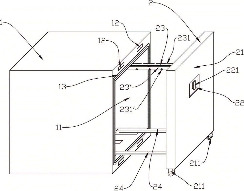
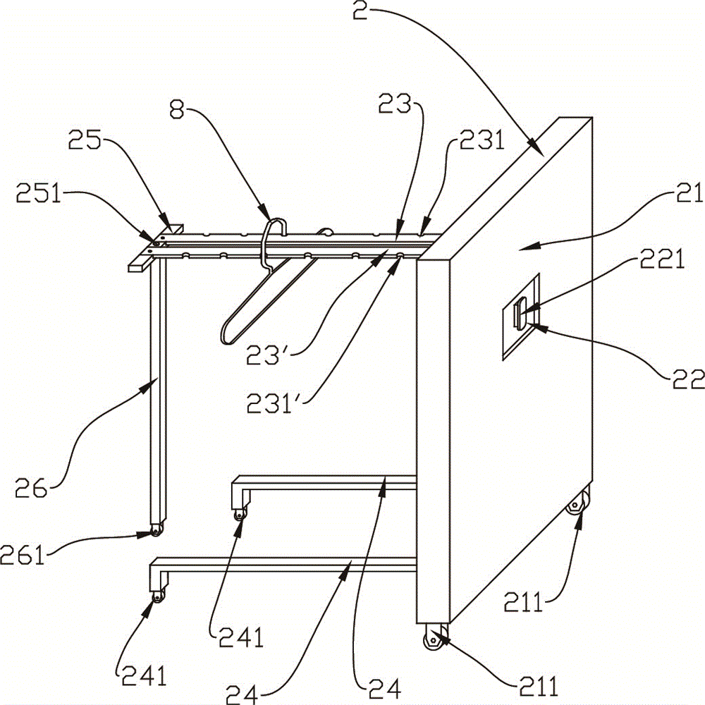
[0034] See Figure 1 to Figure 7, a drying device, comprising a housing 1 and a sliding plate frame 2, an opening 11 is provided on one side of the housing 1, and the sliding plate frame 2 includes a movable plate 21 that can be matched and sealed with the opening 11. The sealing method is as follows: the end surface of the housing 1 in contact with the movable plate 21 is provided with a magnetic suction block 12 and a sealing strip 13, the magnetic suction block 12 is adsorbed to ensure that it will not be easily disengaged, and the sealing strip 13 is used to ensure air tightness .

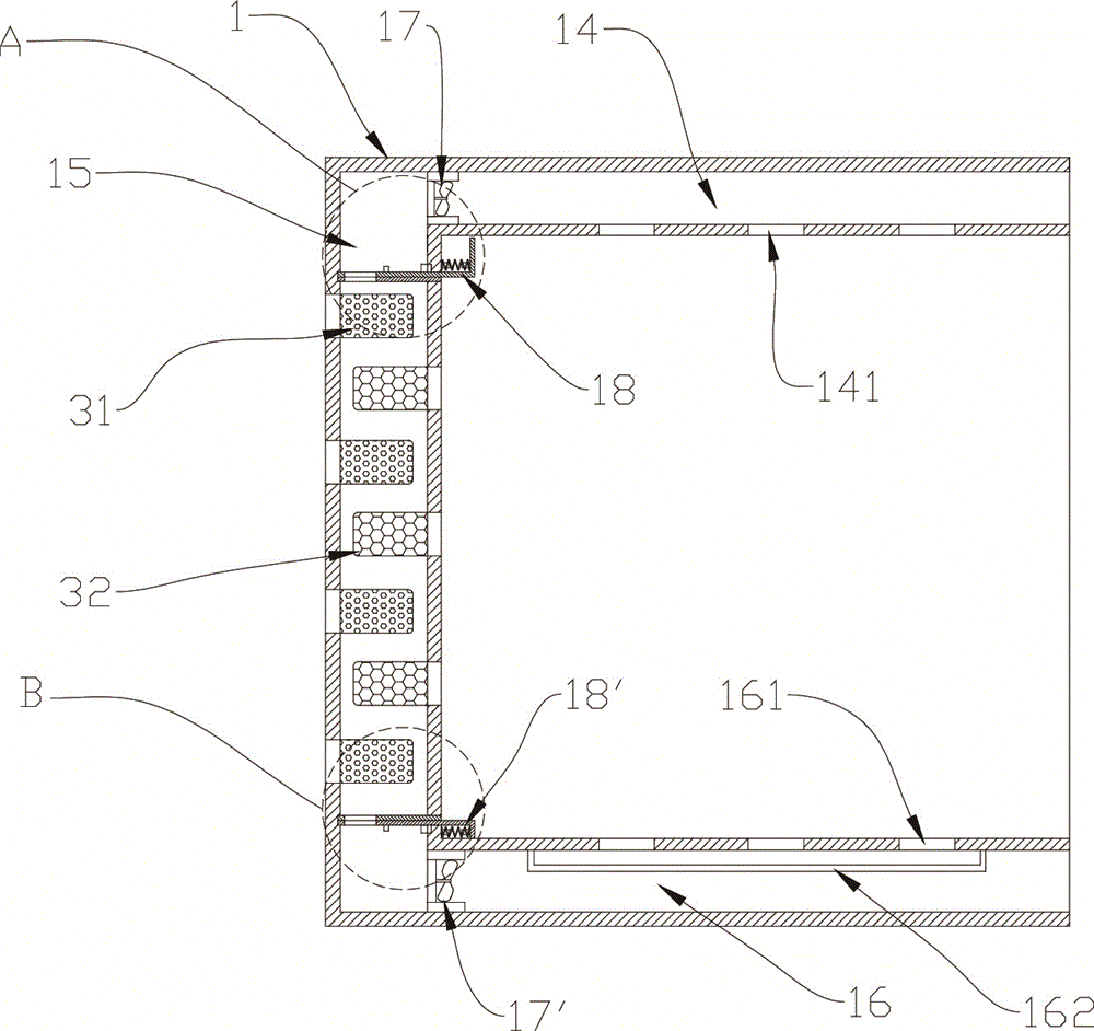
[0035] In this embodiment, the side of the movable plate 21 facing the opening 11 is provided with a clothes rail and a support rod 24, and a hollow layer is provided in the housing 1, and the hollow layer includes an upper hollow layer 14, a side hollow layer 15 and the low...


PUM


Abstract

A drying device comprises a shell and a sliding plate frame. An opening is formed in one face of the shell, the sliding plate frame comprises a movable plate which can seal the opening in a matched mode, the side, facing the opening, of the movable plate is provided with clothes hanging rods and supporting rods, the clothes hanging rods comprise the first clothes hanging rod and the second clothes hanging rod, one end of the first clothes hanging rod and one end of the second clothes hanging rod are connected to the movable plate, the other end of the first clothes hanging rod and the other end of the second clothes hanging rod are connected to a fixing piece, and the fixing piece is connected with the second supporting rod in a rotating mode. A motor is arranged inside the movable plate, a first eccentric rotating block and a second eccentric rotating block are connected to an output shaft of the motor, and the eccentric positions of the first eccentric rotating block and the second eccentric rotating block are arranged reversely. A hollow layer is arranged inside the shell, fans, a drying agent box, an adsorbing agent box, an electric heating device and a closing mechanism are arranged inside the hollow layer, and the drying agent box and the adsorbing agent box are sealed after the closing mechanism is closed. In the drying process, clothes will not wrinkle, peculiar smell on the clothes will not disperse, drying efficiency is high, the utilization rate of hot air is high, and energy is saved.

Description

technical field [0001] The invention belongs to the field of household appliances, and in particular relates to an energy-saving and high-efficiency clothes drying device. Background technique [0002] With the development of the society, more and more home appliances have entered the homes of ordinary people, among which, equipment for drying clothes is a relatively common home appliance. Generally, a clothes dryer dries wet clothes placed therein by continuously blowing hot air into the inside of the drying tub. [0003] The current clothes dryers are mainly drum-type clothes dryers, which directly put the clothes after washing in the washing machine into the dryer for drying. This method is more in line with the usage habits of Europeans and Americans. The washed clothes are hung in the sun to dry. However, sometimes, due to weather conditions, such as cloudy days or sudden rain, the clothes exposed outside cannot be completely dried or are wet by rain again. At this ti...

Claims


Application Information

Patent Timeline
IPC IPC(8): D06F58/10D06F58/20
CPCD06F58/10D06F58/20D06F58/26
Inventor 姚奇富
Owner ZHEJIANG BUSINESS TECH INST
Features
  • Generate Ideas
  • Intellectual Property
  • Life Sciences
  • Materials
  • Tech Scout
  • Unparalleled Data Quality
  • Higher Quality Content
  • 60% Fewer Hallucinations
Learn More