Infrared focal plane detector component

A technology of detector components and infrared focal planes, which is applied in the direction of instruments, measuring devices, scientific instruments, etc., can solve problems such as correction of complex athermalization means, and achieve the effect of improving adaptability and self-radiation control

Inactive Publication Date: 2015-04-22
11TH RES INST OF CHINA ELECTRONICS TECH GROUP CORP
View PDF7 Cites 12 Cited by
  • Summary
  • Abstract
  • Description
  • Claims
  • Application Information

AI Technical Summary

Problems solved by technology

Under the conventional design concept, only complex athermalization methods can be used to correct and compensate
[0006] Aiming at the low temperature, m

Method used


Image

  • Infrared focal plane detector component
  • Infrared focal plane detector component

Examples


Embodiment 1

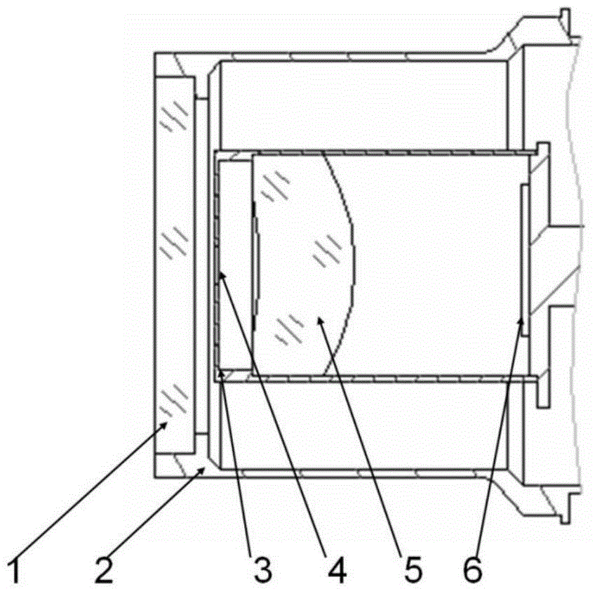
[0023] figure 1 is a schematic structural diagram of an infrared focal plane detector assembly according to Embodiment 1 of the present invention, as figure 1 As shown, the infrared focal plane detector assembly includes: an imaging optical component, a cold screen, and a Dewar, wherein the imaging optical component includes an objective lens and a cold diaphragm, which are integrated inside the above-mentioned Dewar; the objective lens is set as a window of the above-mentioned Dewar, or, The above-mentioned objective lens is glued on the above-mentioned cold screen; the cold diaphragm is arranged on the above-mentioned cold screen; wherein, the above-mentioned cold screen and the above-mentioned window seat of the Dewar are the supporting parts of the above-mentioned imaging optical components.

[0024] There are two implementations for the location of the objective lens, one is that the objective lens is placed on the window of the Dewar, and the other is that the objective ...

Embodiment 2

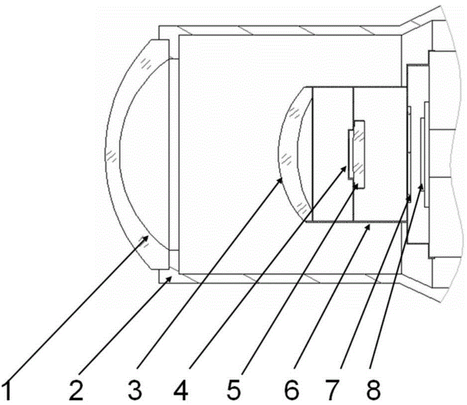
[0035] This embodiment introduces the second implementation manner of the above-mentioned objective lens. figure 2 It is a structural schematic diagram of the infrared focal plane detector assembly of Embodiment 2 of the present invention, as figure 2 As shown, the objective lens includes objective lens 1, objective lens 2, and objective lens 3; the window of Dewar adopts the above-mentioned objective lens 1 to expand the field of view of the optical system; the objective lens 2 and the above-mentioned objective lens 3 are bonded on the cold screen to ensure its correct optical position, and cools the objective lens to a stable temperature by conduction through the aforementioned cold shield. The imaging optical component also includes a low-temperature filter, which is bonded to the above-mentioned cold screen to ensure its correct optical position, and cools the objective lens to a stable temperature through the conduction of the above-mentioned cold screen.

[0036] Pref...


PUM


Abstract

The invention discloses an infrared focal plane detector component. The infrared focal plane detector component comprises imaging optical parts, a cold shield and a dewar, wherein the imaging optical parts comprise an objective lens and a cold stop which are integrated in the interior of the dewar; the objective lens is arranged on the window of the dewar or bonded with the cold shield; the cold stop is arranged on the cold shield, and the cold shield and the window seat of the dewar are the support pieces of the imaging optical parts. The infrared focal plane detector component solves the problems of the low temperature, the miniaturization and the athermalization of an infrared optical system in the correlation technique, the infrared imaging optical parts are integrated in the detector dewar component and made to be in a constant low temperature environment, therefore the self-emitted radiation of the optical system can be effectively controlled, the adaptive capacity to environmental temperature variations is greatly improved, and the optical system is significantly superior to a conventional imaging system in volume and weight.

Description

technical field [0001] The invention relates to the field of photoelectric technology, in particular to an infrared focal plane detector assembly. Background technique [0002] The application fields of this patent are mainly infrared imaging systems for aerospace and infrared imaging systems carried on small platforms such as drones and missiles. [0003] Space is a high-vacuum, low-temperature environment of about 3K, and the target signal to be detected is very weak. In this case, the background radiation of the infrared optical system itself will seriously affect the sensitivity of the infrared imaging system. In order to reduce this thermal noise and play the role of the background limit detector, the optical system and its related components must be cooled to a certain extent. In order to effectively reduce the background photon flux. At the same time, reducing the temperature of the infrared optical system can also shield the thermal interference from outside the sy...

Claims


Application Information

Patent Timeline
IPC IPC(8): G01J5/00G01J5/08
Inventor 王春生周立庆虞孝舜东海杰孟令超
Owner 11TH RES INST OF CHINA ELECTRONICS TECH GROUP CORP
Why Eureka
Try Eureka