
Device and method for measuring magnetic induction intensity B through time domain electromagnetic method

A magnetic induction, time domain electromagnetic technology, applied in the field of geophysical exploration equipment, can solve the problems of inferior, unable to give inversion interpretation model parameters, unable to accurately measure the change curve of magnetic induction B, etc., to achieve high accuracy and Reliability, the effect of improving accuracy and reliability

Inactive Publication Date: 2015-04-22
JILIN UNIV
View PDF7 Cites 8 Cited by
  • Summary
  • Abstract
  • Description
  • Claims
  • Application Information

AI Technical Summary

Problems solved by technology

[0005] The devices and methods of the above-mentioned inventions can improve the measurement accuracy, the reliability and accuracy of data inversion interpretation to a certain extent, but there are some shortcomings. They all collect the voltage signal induced by the receiving coil according to Faraday's law of electromagnetic induction , come out In the inversion process, the relationship curve of the change of magnetic induction intensity B with time t is not as accurate and reliable as the relationship curve of the change of magnetic induction intensity B with time t; neither can accurately measure the relationship curve of the change of magnetic induction intensity B with time t, and cannot give the most Optimal Inversion Interpretation Model Parameters

Method used


Image

  • Device and method for measuring magnetic induction intensity B through time domain electromagnetic method
  • Device and method for measuring magnetic induction intensity B through time domain electromagnetic method
  • Device and method for measuring magnetic induction intensity B through time domain electromagnetic method

Examples


Embodiment Construction

[0032] Below in conjunction with accompanying drawing and embodiment the present invention is described in further detail:

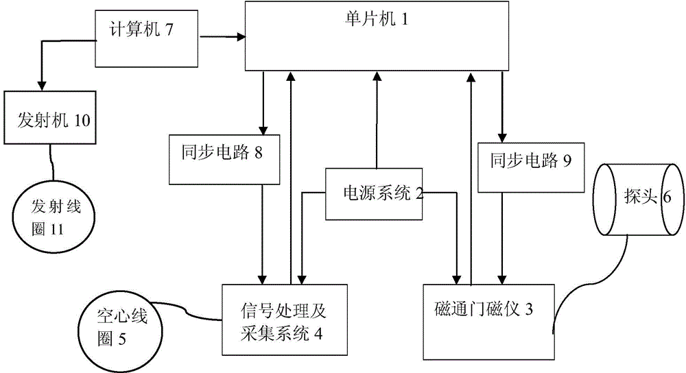
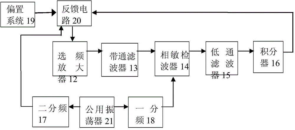
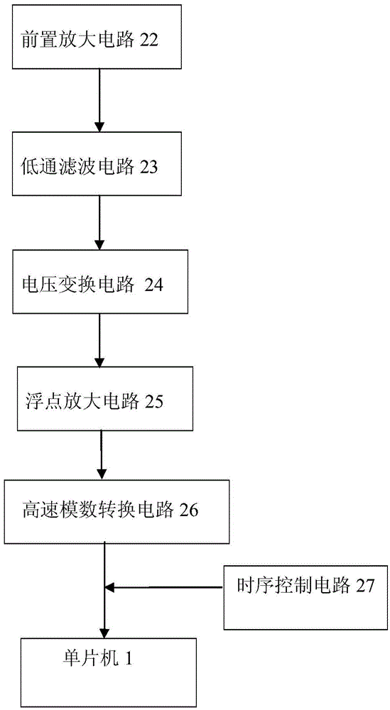
[0033]A measuring device for the magnetic induction intensity B of a time-domain electromagnetic method is that a single-chip microcomputer 1 is connected to a fluxgate magnetometer 3 and a signal processing and acquisition system 4 through a power supply system 2, and the single-chip microcomputer 1 is connected to the fluxgate magnetometer 3 through a synchronous circuit 9, The probe 6 is connected to the single-chip microcomputer 1 through the gate magnetometer 3, the single-chip microcomputer 1 is connected to the signal processing and acquisition system 4 through the synchronous circuit 8, the hollow coil 5 is connected to the single-chip microcomputer 1 through the signal processing and acquisition system 4, and the transmitting coil 11 is connected to the single-chip microcomputer 1 through the transmitter 10 and The computer 7 is connected with th...


PUM


Abstract

The invention relates to a device and method for measuring a magnetic induction intensity B through a time domain electromagnetic method. The device is formed in the mode that a single-chip microcomputer is connected with a flux-gate magnetometer and a signal processing and collecting system through a power supply system, the single-chip microcomputer is connected with an open gate magnetometer through a synchronous circuit, a probe is connected with the single-chip microcomputer through the open gate magnetometer, the single-chip microcomputer is connected with the signal processing and collecting system through the synchronous circuit, a hollow coil is connected with the single-chip microcomputer through the signal processing and collecting system, and a transmitting coil is connected with the single-chip microcomputer through a transmitter and a computer. By means of combined application of the hollow coil and the flux-gate magnetometer, the flux-gate magnetometer with a good low-frequency characteristic is used for measuring a relatively stable magnetic field, the hollow coil with a good high-frequency characteristic, interpolation and integral computation are used for measuring magnetic fields which change quickly, a change relation curve of the magnetic induction intensity B along with the time can be precisely measured, good inversion model data are obtained, and accuracy and reliability of inverse interpretation are improved.

Description

technical field [0001] The invention relates to a geophysical exploration equipment and method, in particular to a measuring device and method for the magnetic induction intensity B of the time-domain electromagnetic method. Background technique [0002] Time-domain electromagnetic method (TEM) is a commonly used geophysical prospecting method. During the detection process of time-domain electromagnetic method, the signal received by the receiver is the voltage signal induced by the receiving coil, that is, is the number of turns of the coil, A is the area of ​​the coil), in the process of inversion interpretation, the detection results are usually converted into apparent resistivity curves to infer the underground geological conditions. For the calculation of apparent resistivity, it can be divided into two categories, one is the rate of change of magnetic induction intensity Calculate the apparent resistivity, the other is to use the magnetic induction B to calculate th...

Claims


Application Information

Patent Timeline
IPC IPC(8): G01R33/04G01V3/08
Inventor 尚新磊彭良玉孙淑琴巨长磊蔡敏徐奡澍贺岩
Owner JILIN UNIV
Learn More