
Electronic device posture adjustment device based on bistable-state structure

An electronic device, bistable technology, applied to devices with sensors, sub-office devices, piezoelectric effect/electrostrictive or magnetostrictive motors, etc., can solve the problem of short duration of high-speed rotation and power consumption of vibration motors Can be large, not easy to miniaturize and other problems, to achieve the effect of easy miniaturization, large attitude adjustment force, simple and compact structure

Inactive Publication Date: 2015-04-22
张文明 +2
View PDF8 Cites 26 Cited by
  • Summary
  • Abstract
  • Description
  • Claims
  • Application Information

AI Technical Summary

Problems solved by technology

These patents give a variety of solutions, including moving a weighted component in the device to adjust the center of the device, or popping a protective bracket somewhere in the device housing, or quickly releasing a can of air, or Either lock the inserted earphone plug or take other protective measures to protect the equipment. Most of the above solutions are difficult to apply in practice. The more realistic method is to adjust the electronic equipment in the air through a vibration motor with eccentric mass. Attitude, to avoid fragile and important components directly colliding with the ground, but the vibration motor consumes a lot of energy, provides limited torque, high-speed rotation lasts for a short time, is easy to burn, and is not easy to be miniaturized, so in the implementation there are still many difficulties

Method used


Image

  • Electronic device posture adjustment device based on bistable-state structure
  • Electronic device posture adjustment device based on bistable-state structure
  • Electronic device posture adjustment device based on bistable-state structure

Examples


Embodiment Construction

[0027] Below in conjunction with accompanying drawing, the present invention will be further described as follows:

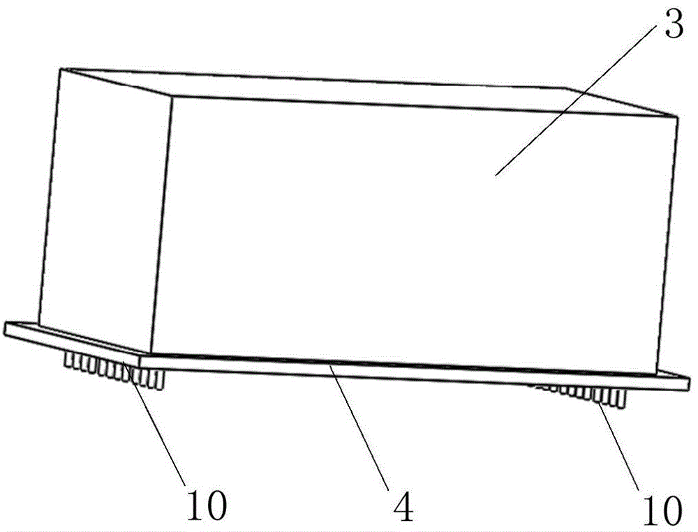
[0028] as attached figure 1 As shown, it is a schematic diagram of the appearance of the present invention, wherein the shielding cover 3 is made of 0.2mm thick stainless steel or nickel-nickel copper, which can be fixed or detachable to prevent electromagnetic interference (EMI) and shield other components inside the smart phone Function: the PCB base plate 4 integrates signal acquisition and processing circuits; the pin 10 fixes the attitude adjustment unit on the PCB base plate 4 and functions as power and signal transmission.

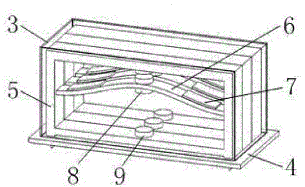
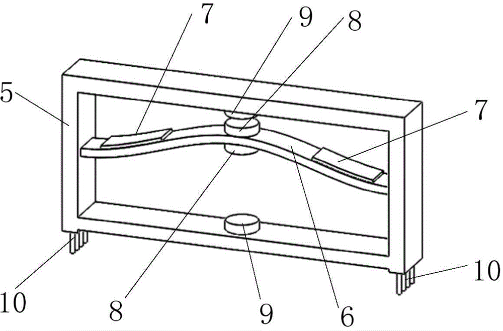
[0029] as attached figure 2 As shown, the posture adjuster includes a shield 3 and a PCB bottom plate 4, the PCB bottom 4 is connected to the bottom of the shield 3, and the shield 3 and the PCB bottom 4 are packaged with an attitude adjustment unit based on the bistable jump characteristic. There are at least two adjustment units,...


PUM


Abstract

The invention relates to an electronic device posture adjustment device based on a bistable-state structure. The electronic device posture adjustment device comprises a shielding cover (3) and a PCB bottom plate (4), a posture adjustment unit is packaged in the shielding cover (3) and comprises a frame (5), bistable-state elastic beams (6) and piezoelectric units (7), the bistable-state elastic beams (6) are fixed to the inner side of the frame (5) and has the upwards-convex state and the downwards-concave state, the piezoelectric units (7) are symmetrically spliced to the left sides and the right sides of the bistable-state elastic beams (6), permanent magnets (8) are fixed to the middles of the bistable-state elastic beams (6), and electromagnets (9) are arranged above and below the permanent magnets (8) and fixed to the frame (5). By means of the electronic device posture adjustment device, the external vibration energy can be collected, the in-air posture of a portable electronic device in the falling process can be further adjusted, and an impacting resistant portion of the portable electronic device is in contact with the ground firstly so that the effect of protecting a fragile part can be achieved.

Description

[technical field] [0001] The invention relates to the field of micro-miniature actuators and new energy technologies, in particular to an electronic device attitude regulator based on a bistable structure. [Background technique] [0002] With the development of mobile Internet technology, the use of portable electronic devices is becoming more and more common. They are small, light, powerful, easy to hold in your hand, and put them in pockets, purses or bags. essential items. Mobile electronic devices such as smartphones and tablet computers have gradually become necessary items for people to carry with them due to their powerful functions and superior portability. Falling state. For example, an electronic device placed on a counter or table may slip due to external impact. When an electronic device is dropped to the ground, its surface is subjected to a large impact, and serious damage is likely to occur even if the electronic device is equipped with a protective case or...

Claims


Application Information

Patent Timeline
IPC IPC(8): G06F1/16H02N2/18
CPCG06F1/1626G06F1/1656G06F1/1694G06F2200/1633H02N2/183H04M1/185H04M2250/12
Inventor 李汶柏张文明邹鸿翔
Owner 张文明
Learn More