Comb line slow wave structure working on high-order pass band

A slow-wave structure and comb-line technology, applied in the field of microwave vacuum electronic devices, can solve the problems of poor high-frequency and high-power performance, and achieve the effect of improving power performance

Active Publication Date: 2015-04-22
NO 12 RES INST OF CETC
View PDF2 Cites 11 Cited by
  • Summary
  • Abstract
  • Description
  • Claims
  • Application Information

AI Technical Summary

Problems solved by technology

[0005] The technical problem to be solved by the present invention is to provide a comb-line slow-wave structure working in a high-o...

Method used


Image

  • Comb line slow wave structure working on high-order pass band
  • Comb line slow wave structure working on high-order pass band
  • Comb line slow wave structure working on high-order pass band

Examples


Embodiment Construction

[0021] The present invention will be described in further detail below in conjunction with the accompanying drawings and embodiments. It should be understood that the specific embodiments described here are only used to explain the present invention, not to limit the present invention.

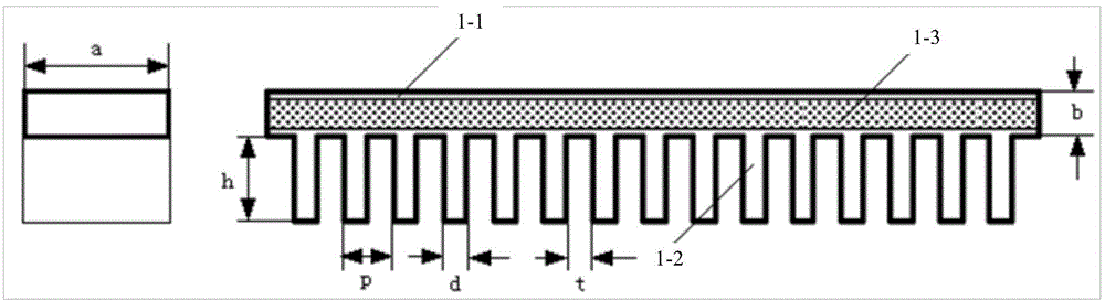
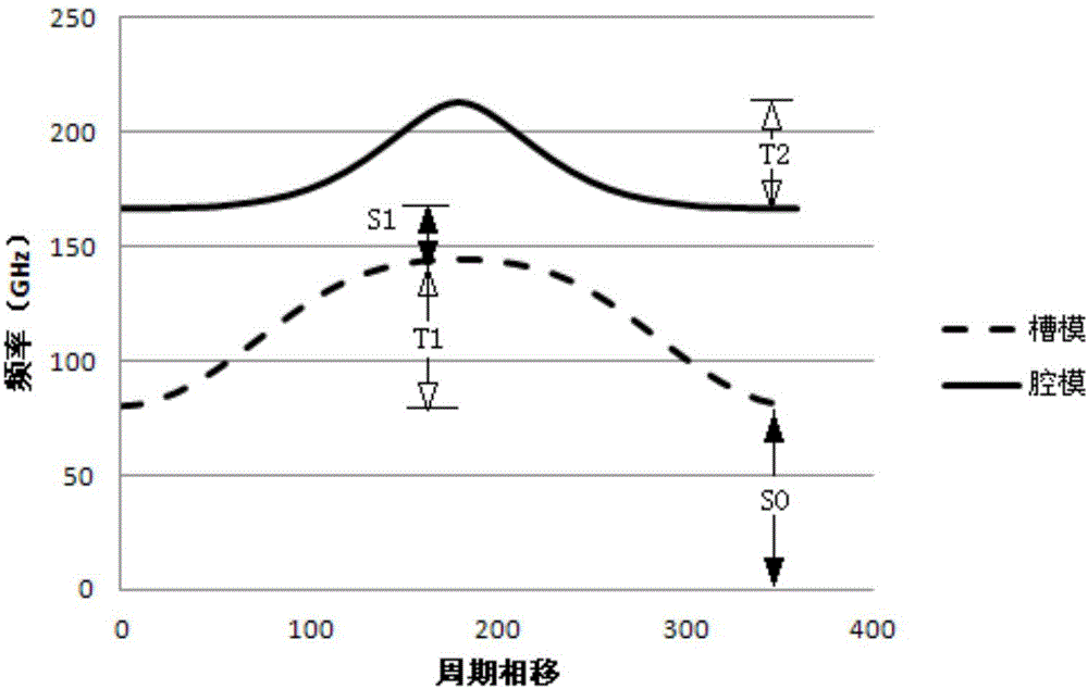
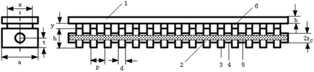
[0022] In order to obtain a slow wave structure suitable for high-power terahertz return wave oscillators, the present invention sets the interaction area on the comb line while maintaining the inherent micromachining compatibility of the comb line, good cold characteristic parameters and simple coupling advantages. In the cavity mode area, the slot mode area and the cavity mode area are connected through a small-sized waveguide as a filter circuit, and the slot mode electromagnetic field is isolated from the interaction area by using its lower cut-off characteristics, so as to solve the possible mode competition in the low passband and make the electron injection Only the required cavity-mode...


PUM


Abstract

The invention discloses a comb line slow wave structure working on a high-order pass band. The comb line slow wave structure comprises a cavity mode area, and a rectangular resonant cavity array is composed of a series of straight waveguides; electron beam channels penetrate through the rectangular resonant cavity array composed of the straight waveguides and used for transmitting electron beams; and the mutual action of the beams and waves occurs in the cavity mode area. The slow wave structure has the advantages of being suitable for the working of the high-order pass band, and free of the influence of low pass band mode competition, and the power performance of a terahertz backward wave oscillator can be improved.

Description

technical field [0001] The invention relates to the field of microwave vacuum electronic devices, in particular to a comb-line slow-wave structure working in a high-order passband. Background technique [0002] With the rapid development of terahertz science and technology, the requirements for terahertz radiation sources are increasing. Whether a practical, high-power, tunable terahertz radiation source can be developed plays a vital role in the development of terahertz science and technology. . The back-wave oscillator is a microwave vacuum electronic device. It is a commonly used millimeter-wave source and a terahertz radiation source with great development potential. Electronic tuning is realized in a very wide frequency band, but with the increase of frequency, the small size brings great technical challenges to the electron optical system and high frequency system, causing the power level of the return wave oscillator to drop rapidly, which cannot meet High-power app...

Claims


Application Information

Patent Timeline
IPC IPC(8): H01J23/28
CPCH01J23/28H01J25/46
Inventor 蔡军冯进军
Owner NO 12 RES INST OF CETC
Why Eureka
Try Eureka