Anti-condensation device with self-adaptation control and control method

A technology of self-adaptive control and control method, applied in the direction of non-electric variable control, control/regulation system, simultaneous control of multiple variables, etc., can solve the problems of energy waste, blockage of air duct, and large consumption of electric energy resources, etc., to avoid easy The effect of blocking the air duct and reducing power consumption

Inactive Publication Date: 2015-04-22
ELECTRIC POWER RES INST OF GUANGXI POWER GRID CO LTD
View PDF10 Cites 12 Cited by
  • Summary
  • Abstract
  • Description
  • Claims
  • Application Information

AI Technical Summary

Problems solved by technology

Therefore, in actual operation, it is often found that serious condensation still occurs in the cabinet where the heating dehumidifier is installed, which endangers the normal operation of electrical equipment; at the same time, the heating dehumidifier mainly relies on electric energy for heating, which consumes a lot Power resources, high cost of dehumidification
[0004] In response to the above situation, more and more manufacturers have successively developed anti-condensation systems based on electronic condensation dehumidification, but their control methods for the internal core part-refrigeration components are single, and most manufacturers only use ambient humidity and humidity thresholds. This single control method cannot solve the problem of low temperature and high humidity—in the case of low temperature and high humidity, it is easy to form frost at the cold end of the continuous low temperature, and even block the air duct in severe cases , affect the dehumidification effect
At the same time, under different environmental conditions, the electronic condenser continues to work, and the temperature of the cold end is always reduced to the minimum. Since the refrigeration efficiency of the electronic condenser is not high, it inevitably causes a waste of energy, and it does not have a great deal of energy. good dehumidification effect

Method used


Image

  • Anti-condensation device with self-adaptation control and control method
  • Anti-condensation device with self-adaptation control and control method
  • Anti-condensation device with self-adaptation control and control method

Examples


Embodiment Construction

[0024] The present invention will be further explained below in conjunction with the accompanying drawings and specific embodiments. Those skilled in the art should understand that the following specific embodiments are only used to illustrate the present invention and are not intended to limit the scope of the present invention.

[0025] The model of the electrical component adopted in the present embodiment:

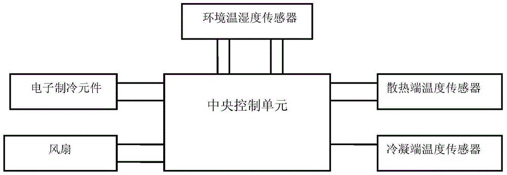
[0026] Environmental temperature and humidity sensor: SI7005 digital calibration-free temperature and humidity sensor

[0027] Condensing end temperature sensor, cooling end temperature sensor: NTC thermistor

[0028] Electronic cooling element: TE12705

[0029] Central control unit main control chip: C8051F3xx series MCU

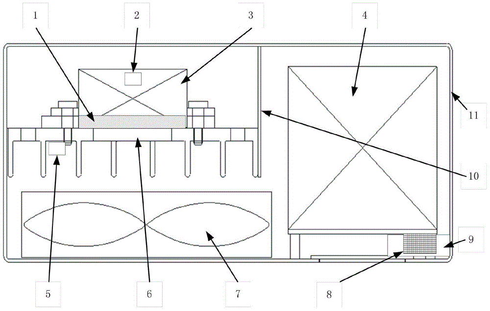
[0030] Such as figure 1 As shown, an adaptive control anti-condensation device includes a housing, an electronic condensation assembly installed inside it, and a central control unit. The shell is divided into two chambers by a partition, and t...


PUM


Abstract

The invention discloses an anti-condensation device with self-adaptation control and a control method. The anti-condensation device with self-adaptation control and the control method comprise a temperature and humidity sensor which is used for detecting the environmental temperature and humidity, an electronic condensation component which is used for condensation dehumidification, a temperature sensor which is used for detecting the temperature of a condensation end, a temperature sensor which is used for detecting the temperature of a heat dissipation end, and a central control unit which is used for controlling the electronic condensation component. The electronic condensation component comprises the condensation end, the heat dissipation end, an electronic refrigeration element and a heat dissipation fan. The central control unit is provided with a firmware program. The central control unit is characterized in that the central control unit can monitor the environmental temperature and humidity sensor when the anti-condensation device is in the dehumidification mode, and search in a 'dew point temperature table' according to the obtained environmental temperature and humidity values to obtain the corresponding dew point temperature value; meanwhile, comparison between the temperature value of the condensation end and the temperature value of a dew point is conducted to drive the start-up and shut-down of the electronic refrigeration element. Therefore, the power consumption can be decreased, and the dehumidifying effect can be optimized under different circumstances.

Description

technical field [0001] The invention relates to a temperature and humidity control device, in particular to the field of temperature and humidity control of a power cabinet. Background technique [0002] Power cabinets refer to power distribution equipment or other electrical equipment installed inside in the power industry. The internal environment of the cabinet has certain requirements for temperature and humidity. The temperature and humidity of the air should be controlled below a certain value. Usually In this state, a dehumidification and temperature control device should be installed in the cabinet. [0003] At present, the electric power industry mainly uses the electric heating method to control the relative humidity in the cabinet—that is, by heating the air, the hot air has a higher saturated water vapor partial pressure, thereby reducing the relative humidity of the air. However, the water vapor in the air still exists in the cabinet. When the heating stops or ...

Claims


Application Information

Patent Timeline
Patent Type & Authority Applications(China)
IPC IPC(8): H02B1/56G05D27/02
CPCH02B1/565G05D27/02H02B1/24
Inventor 罗宗昌朱立平黄云光刘陈瑶唐彬张龙飞
Owner ELECTRIC POWER RES INST OF GUANGXI POWER GRID CO LTD
Why Eureka
Try Eureka