
Charge protection device and method in defibrillation system

A charging protection and charging power supply technology, applied in the medical field, can solve problems such as charging failure, delay in patient rescue, and time delay

Active Publication Date: 2017-02-22
SHENZHEN COMEN MEDICAL INSTR
View PDF3 Cites 0 Cited by
  • Summary
  • Abstract
  • Description
  • Claims
  • Application Information

AI Technical Summary

Problems solved by technology

[0005] The deficiencies of traditional defibrillation equipment for charging control are mainly the following points. First, the charging control is carried out through AD sampling capacitor voltage. When the target voltage is reached, the charging is stopped. There is no real-time and precise control of the charging process. When the charging circuit When a fault occurs, it is often necessary to wait for a certain period of time to find that the charging has failed, and a charging overtime error alarm is generated, usually 30s charging overtime alarm, which greatly delays the time and delays the rescue of the patient; In terms of voltage protection, the traditional defibrillation monitor basically sets the overvoltage protection point of the energy storage capacitor to the highest voltage of the energy storage device, but lacks the setting of overvoltage protection for each energy level. , due to circuit failure, the energy storage capacitor may generate and store an excessively high voltage, which may damage the patient when cardioverting the patient

Method used


Image

  • Charge protection device and method in defibrillation system
  • Charge protection device and method in defibrillation system
  • Charge protection device and method in defibrillation system

Examples


Embodiment Construction

[0043] In order to make the technical solutions and advantages of the present invention clearer, the present invention will be further described in detail below in conjunction with the accompanying drawings and embodiments. It should be understood that the specific embodiments described here are only used to explain the present invention, not to limit the present invention.

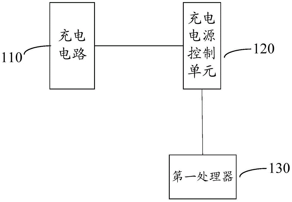
[0044] Such as figure 1 As shown, a charging protection device in a defibrillation system includes a charging circuit 110, a charging power control unit 120 and a first processor 130, the charging circuit 110 is connected to the charging power control unit 120, and the charging power control unit 120 is connected to the first processor Device 130 is connected.

[0045] The first processor 130 is used to obtain the voltage of the charging capacitor in the charging circuit every preset time, and judge whether the charging voltage is valid. After the first processor 130 judges that the charging voltage obta...


PUM


Abstract

The invention provides a charging protection device and method in a defibrillation system. The charging protection device comprises a charging circuit, a charging power supply control unit and a first processor. Dual judgment is conducted through the first processor, wherein firstly, by judging whether the obtained charging voltage is valid or not, line faults are eliminated, and the obtained voltage is the dead voltage; after the obtained charging voltage is judged to be valid, whether the obtained charging voltage meets the preset relation curve of the charging voltage and time or not is judged, charging is determined to be abnormal if the obtained charging voltage is judged not to meet the relation curve of the charging voltage and time, the first processor sends a stop signal to the charging power supply control unit, and the charging power supply control unit controls the charging circuit to stop conducing charging. By means of the dual judgment conducted through the first processor, the real-time and precise control over the charging process of defibrillation is achieved, and when charging circuit faults or abnormal charging happens, the abnormal charging can be found in real time.

Description

technical field [0001] The invention relates to the field of medical technology, in particular to a charging protection device and method in a defibrillation system. Background technique [0002] Ventricular fibrillation, referred to as ventricular fibrillation or ventricular fibrillation, is the most serious form of fatal cardiac arrhythmia in which the normal, regular contraction of the ventricles is replaced by a rapid, irregular flutter due to The ventricular muscle cannot contract effectively, so the blood circulation is interrupted and the blood supply to the brain stops. The patient will immediately lose consciousness and convulsions all over the body. If the normal heart rate cannot be restored quickly, the patient will die soon. So far, electric shock defibrillation is considered to be the most rapid and effective way to terminate ventricular fibrillation. The electric shock defibrillator can generate high-voltage, energy-controllable pulse current to act on the hea...

Claims


Application Information

Patent Timeline
Patent Type & Authority Patents(China)
IPC IPC(8): A61N1/39H02J7/00
Inventor 王晶尹鹏易明生
Owner SHENZHEN COMEN MEDICAL INSTR
Learn More