Driving pin shaft processing method

A processing method and pin technology, applied in metal processing equipment, metal processing mechanical parts, manufacturing tools, etc., can solve problems such as low production efficiency, and achieve the effects of improving production efficiency, accurate clamping and positioning, and reducing processing costs.

Inactive Publication Date: 2015-04-29
LIUZHOU JULONG TECH
View PDF5 Cites 6 Cited by
  • Summary
  • Abstract
  • Description
  • Claims
  • Application Information

AI Technical Summary

Problems solved by technology

[0003] The technical problem to be solved by the present invention is to provide a processing method of a transmission pin, so as to solve the problem that only one transmission pin can be clamped and processed each time, and the production efficiency is low

Method used


Image

  • Driving pin shaft processing method
  • Driving pin shaft processing method
  • Driving pin shaft processing method

Examples


Embodiment Construction

[0017] The present invention will be described in further detail below in conjunction with accompanying drawing embodiment:

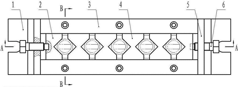
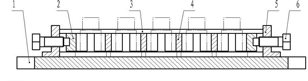
[0018] Such as figure 2 , image 3 , Figure 4 The shown multi-station milling fixture includes a bottom plate 1, the two ends of the bottom plate 1 are provided with bolt installation slots, the bottom plate 1 is provided with a long slot and two opposite side baffles on both sides of the long slot 3. The upper ends of the two side baffles 3 are provided with protruding lines protruding inwardly, and the two side baffles 3 are respectively connected to the bottom plate 1 by bolts, and two first Clamping plate 2, the inner end of the first clamping plate 2 is provided with a V-shaped clamping surface, and the outer end is provided with a screw limit hole; between the two first clamping plates 2 there is a sliding connection with the side baffle 3 There are four second clamping plates 4, and the two ends of the second clamping plate 4 are provided wi...


PUM


Abstract

The invention discloses a driving pin shaft processing method and relates to the technical field of machining; a multi-station milling fixture is adopted to process, wherein the multi-station milling fixture comprises a base plate, wherein a long groove and two side baffle plates which are oppositely arranged are arranged on the base plate; convex strips which extend towards inner sides are arranged at the upper ends of the two side baffle plates; two first clamping plates and a plurality of second clamping plates are slidingly connected between the two side baffle plates; V-shaped clamping surfaces are formed at the inner ends of the first clamping plates, and screw limiting holes are formed at the outer ends; V-shaped clamping surfaces are formed at both ends of the second clamping plates; and pre-tightening screws which are fixed on the base plate by virtue of supporting plates are arranged at the outer ends of the first clamping plates. The processing method comprises the following processing steps: A. mounting the fixture; B. mounting workpieces; C. milling a groove; and D. detaching all workpieces. Compared with the prior art, the processing method disclosed by the invention can be used for clamping a plurality of machined parts at one time for milling and processing, so that production efficiency is greatly improved and processing cost is reduced.

Description

technical field [0001] The invention relates to the technical field of mechanical processing, in particular to a processing method for a transmission pin. Background technique [0002] Such as figure 1 One end of the transmission pin shaft 101 shown is provided with a boss, and the other end is provided with a small-diameter section shaft, and the outer end surface of the small-diameter section shaft is provided with a groove. The groove processing of the transmission pin shaft is usually carried out on a milling machine by using a milling fixture. The currently used milling fixture can only clamp one transmission pin shaft, so this processing method of the transmission pin shaft can only clamp and process one transmission pin shaft at a time. The pin shaft has low production efficiency and high processing cost. Contents of the invention [0003] The technical problem to be solved by the present invention is to provide a method for processing a transmission pin, so as to...

Claims


Application Information

Patent Timeline
Patent Type & Authority Applications(China)
IPC IPC(8): B23C3/28B23Q3/06
CPCB23C3/28B23C2220/36B23Q3/061B23Q3/062
Inventor 苏志强谢宇强
Owner LIUZHOU JULONG TECH
Why Eureka
Try Eureka