Piston workblank casting head continuous automatic sawing machine tool and continuous automatic sawing method

A technology for pouring risers and blanks, which is applied in the field of continuous automatic sawing machine tools for pouring and rising of piston blanks, can solve the problems of low work efficiency, large investment and long adjustment time.

Active Publication Date: 2015-04-29
ANHUI WHITE RABBIT POWER
View PDF6 Cites 8 Cited by
  • Summary
  • Abstract
  • Description
  • Claims
  • Application Information

AI Technical Summary

Problems solved by technology

[0002] In the manufacture of pistons, the processing of sprues and risers is an indispensable process. Because it is the processing of billets, there are problems of high labor intensity and low work efficiency. At present, there are two forms in China. The first is to use ordinary The lathe is hydraulically modified, and equipped with special tooling to process the top riser and side runner respectively. It is divided into two processes. This is more common, requiring two machine tools and two operators. Material transfer is also required in the middle of the process.
The second case is to use a top riser special machine and a band saw machine. First, the band saw machine is used to complete the processing of the side runner without special fixtures. The efficiency is high, but these two forms use two processes, and the overall efficiency is not very high. In foreign production, it is often done at one time on the sawing machine by using an industrial robot to clamp and turn the manipulator at 90-180 degrees. For the processing of top riser and side sprue, this method also requires manual placement of blanks in order to accurately pick up materials, with high efficiency and low labor intensity, but there are limitations such as large investment and long adjustment time when changing varieties.

Method used


Image

  • Piston workblank casting head continuous automatic sawing machine tool and continuous automatic sawing method
  • Piston workblank casting head continuous automatic sawing machine tool and continuous automatic sawing method
  • Piston workblank casting head continuous automatic sawing machine tool and continuous automatic sawing method

Examples


Embodiment Construction

[0025] The present invention will be further described below in conjunction with the accompanying drawings.

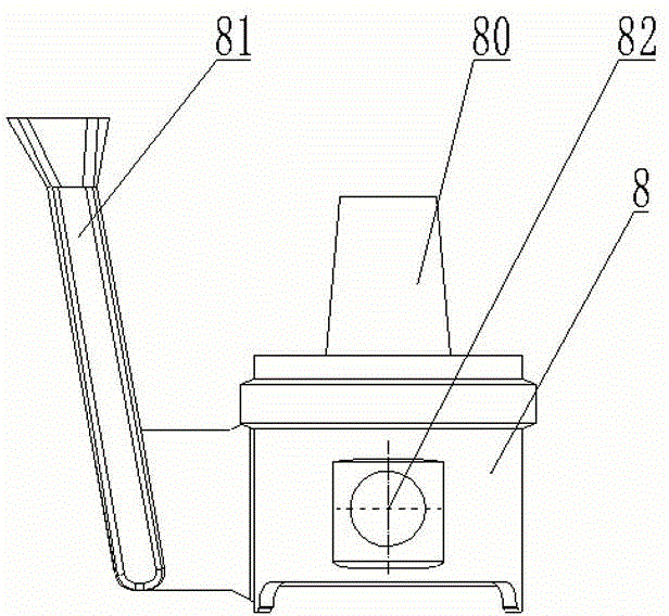
[0026] Such as image 3 It can be seen that the piston blank 8 provided by the casting process includes a top riser 80 and a side runner 81, and the piston blank 8 is processed with a pin hole 82. The continuous automatic sawing machine tool for the piston blank pouring riser provided by the present invention is used for Cut off the top riser 80 and the side runner 81.

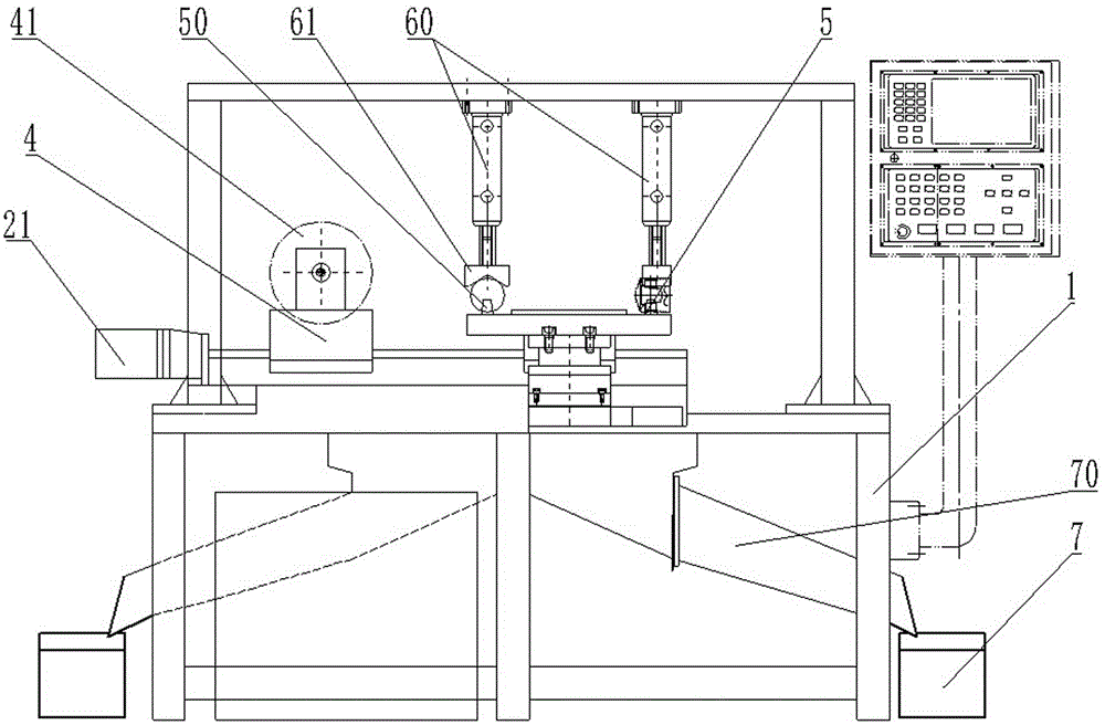
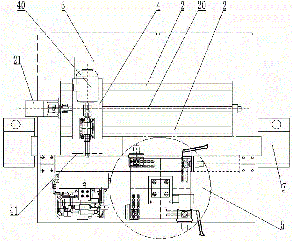
[0027] Such as figure 1 , figure 2 It can be seen that the continuous automatic sawing machine tool for pouring the piston blank into the riser of the present invention includes a bed body 1, the bed body 1 is provided with a Z-direction traveling device, and an X-direction traveling device 3 is movable on the Z-direction traveling device , the X-direction walking device 3 is movable to be provided with a cutting motor carriage 4, the cutting motor carriage 4 is provided with a cutting motor 40, an...


PUM


Abstract

The invention discloses a piston workblank casting head continuous automatic sawing machine tool which comprises a machine tool body. A Z-directional running device is arranged on the machine tool body. The Z-directional running device is movably provided with an X-directional running device which is movably provided with a cutting motor pulling plate. The cutting motor pulling plate is provided with a cutting motor. A cutting tool bit is arranged on the main shaft of the cutting motor. The piston workblank casting head continuous automatic sawing machine tool further comprises a four-station rotating table arranged on the machine tool body. Four location pins are distributed uniformly on the table facet of the four-station rotating table along the circumferential direction. Two sets of clamps are arranged above the machine tool in a matching manner. According to the piston workblank casting head continuous automatic sawing machine tool, the continuous cutting of the piston workblank top riser and the side pouring gate can be achieved; the sawing position is accurate; the degree of automation is high; one person can manage multiple machines, thereby improving the working efficiency.

Description

technical field [0001] The invention relates to a production device for auto parts, in particular to a continuous automatic sawing machine tool for trimming the casting riser of a piston casting blank. Background technique [0002] In the manufacture of pistons, the processing of sprues and risers is an indispensable process. Because it is the processing of billets, there are problems of high labor intensity and low work efficiency. At present, there are two forms in China. The first is to use ordinary The lathe is hydraulically modified, and equipped with special tooling to process the top riser and side runner respectively. It is divided into two processes. This is more common, requiring two machine tools and two operators. Material transfer is also required in the middle of the process. . The second case is to use a top riser special machine and a band saw machine. First, the band saw machine is used to complete the processing of the side runner without special fixtures....

Claims


Application Information

Patent Timeline
Patent Type & Authority Applications(China)
IPC IPC(8): B23D47/00B23D47/04B23D47/08B22D31/00
Inventor 汪舵海张志强
Owner ANHUI WHITE RABBIT POWER
Why Eureka
Try Eureka