
High-speed laser drilling machine capable of charging and discharging automatically

A technology of automatic loading and unloading and laser drilling, which is applied in the direction of laser welding equipment, auxiliary equipment, auxiliary welding equipment, etc., can solve the problems of increased labor costs, large labor consumption, and material damage, so as to save labor costs, avoid damage, The effect of ensuring safety

Active Publication Date: 2015-04-29
鞍山盛雄激光设备有限公司
View PDF6 Cites 24 Cited by
  • Summary
  • Abstract
  • Description
  • Claims
  • Application Information

AI Technical Summary

Problems solved by technology

The laser drilling machine in the prior art generally adopts manual operation for loading and unloading materials, but the efficiency of manual loading and unloading is low, which cannot meet the continuous drilling work of the laser drilling machine; at the same time, when the material is large When it is difficult to manually load and unload materials, it takes a lot of labor, the labor cost increases, and the material is easy to be damaged during the loading and unloading process, resulting in an increase in production costs

Method used


Image

  • High-speed laser drilling machine capable of charging and discharging automatically
  • High-speed laser drilling machine capable of charging and discharging automatically
  • High-speed laser drilling machine capable of charging and discharging automatically

Examples


Embodiment Construction

[0052] The present invention will be described in detail below in conjunction with the accompanying drawings.

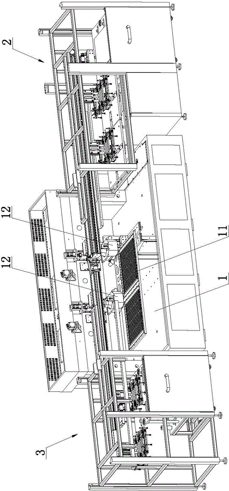
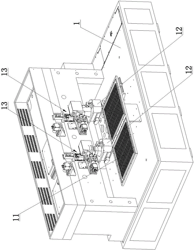
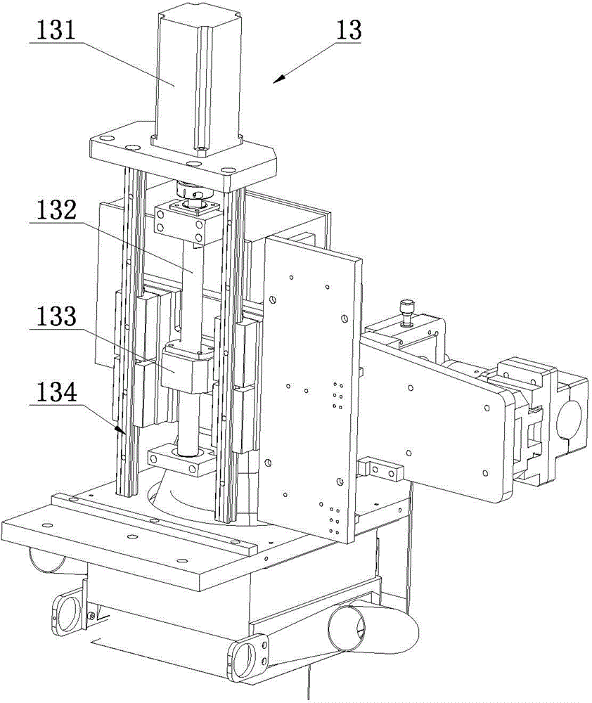
[0053] Such as Figure 1 to Figure 11 As shown, a high-speed laser drilling machine with automatic loading and unloading of the present invention includes a machine platform 1, a feeding device 2 and a feeding device 3, and the machine platform 1 is provided with a vacuum adsorption platform 11 and a high-speed laser vibrating mirror 12. The laser vibrating mirror 12 is located above the vacuum adsorption platform 11, and the machine 1 is also provided with a drilling linear module 13 for driving the high-speed laser vibrating mirror 12 to move along the Z-axis direction; the feeding device 2 includes a feeding frame 21, and the upper The feeding frame 21 is located on one side of the machine platform 1, a feeding box 22 is arranged below the feeding frame 21, a feeding assembly 23 is arranged above the feeding box 22, and several feeding vacuums are arranged on the ...


PUM


Abstract

The invention relates to the technical field of laser drilling equipment, and particularly relates to a high-speed laser drilling machine capable of charging and discharging automatically. The high-speed laser drilling machine comprises a cabinet, a charging device and a discharging device, wherein the cabinet is provided with a vacuum adsorption platform, a high-speed laser galvanometer and a drilling linear module which is used for driving the high-speed laser galvanometer to move along the z-axis direction; the charging device comprises a charging rack, a charging box, a charging component and a charging vacuum suction disc; the charging rack is provided with a charging movable plate and a charging linear module; the charging component is connected with the charging movable plate; the charging box is provided with a charging bearing plate; a charging lifting component is arranged at the rear side of the charging box; the discharging device comprises a discharging rack, a discharging box, a discharging component and a discharging vacuum suction disc; the discharging rack is provided with a discharging movable plate and a discharging linear module; the discharging component is connected with the discharging movable plate; the discharging box is internally provided with a discharging bearing plate; the discharging box is provided with a discharging lifting component. According to the high-speed laser drilling machine, the automatic charging and discharging can be realized; the charging and discharging efficiency is high; materials can be prevented from being damaged.

Description

technical field [0001] The invention relates to the technical field of laser drilling equipment, in particular to a high-speed laser drilling machine with automatic loading and unloading. Background technique [0002] Laser drilling technology has now become a relatively mature industrial processing technology. It can not only drill holes in metals, but also drill holes in some high-hardness and brittle materials, such as ceramic sheets. And before drilling the material with a certain brittleness, the material needs to be placed on the material placement area set by the laser drilling machine, and then the laser is started to drill the material, and the material can be taken out after the drilling is completed. The laser drilling machine in the prior art generally adopts manual operation for loading and unloading materials, but the efficiency of manual loading and unloading is low, which cannot meet the continuous drilling work of the laser drilling machine; at the same time...

Claims


Application Information

Patent Timeline
Patent Type & Authority Applications(China)
IPC IPC(8): B23K26/382B23K26/402B23K26/70B23K37/04
CPCB23K37/04
Inventor 陶雄兵
Owner 鞍山盛雄激光设备有限公司
Learn More