Hybrid drive of a motor vehicle

A technology of hybrid power and driving devices, which is applied in the direction of power devices, hybrid vehicles, pneumatic power devices, etc., can solve the problems of poor transmission efficiency of switching elements, and achieve the effect of saving structural space

Inactive Publication Date: 2015-04-29
ZF FRIEDRICHSHAFEN AG
View PDF11 Cites 6 Cited by
  • Summary
  • Abstract
  • Description
  • Claims
  • Application Information

AI Technical Summary

Problems solved by technology

Disadvantages of this hybrid drive, however, are the greater overall number of shift elements required, the greater number of shift elemen

Method used


Image

  • Hybrid drive of a motor vehicle
  • Hybrid drive of a motor vehicle
  • Hybrid drive of a motor vehicle

Examples


Embodiment Construction

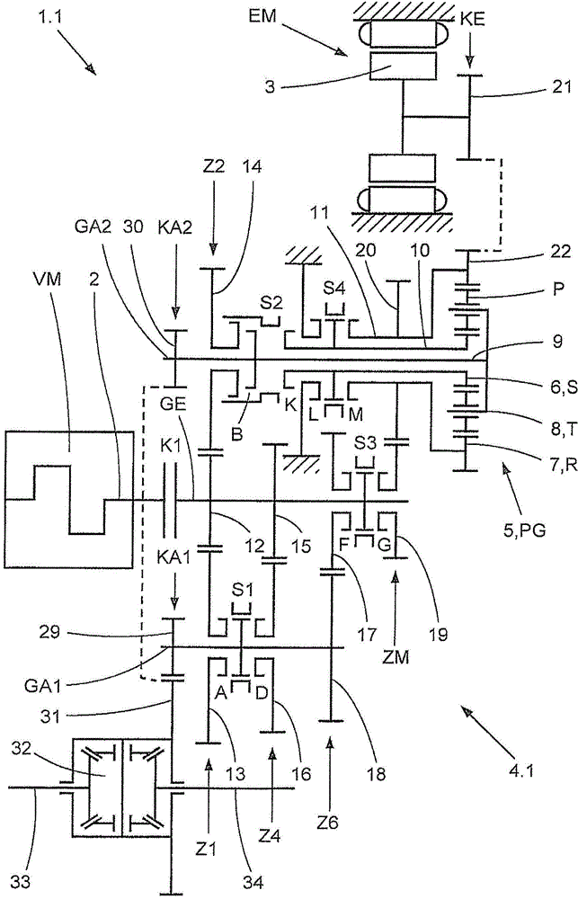
[0044] The hybrid drive device 1.1 according to the invention is figure 1 The first embodiment variant shown schematically in , has an internal combustion engine VM with a drive shaft 2, an electric machine EM with a rotor 3 that can be operated as a motor and as a generator, an electric motor EM implemented in the form of an intermediate shaft with an input The automatic shift transmission 4 . 1 of shaft GE and the two output shafts GA1 , GA2 and the superposition transmission 5 in the form of a planetary gear with two input elements 6 , 7 and an output element 8 .

[0045]The input shaft GE of the shift transmission 4.1 can be connected on the input side to the drive shaft 2 of the internal combustion engine VM via a separating clutch K1 designed as a friction clutch. In the transmission, the input shaft GE of the shift transmission 4.1 can be connected to the first output shaft GA1 via three selectively switchable spur gear stages Z1, Z4, Z6 and can be via another selective...


PUM


Abstract

A hybrid drive of a motor vehicle includes a combustion engine, an electric machine, a gear box, and a superimposed transmission. The gearbox includes an input shaft, and first and second output shafts, and the input shaft is connected to the first and second output shafts via switchable spur gear stages. The superimposed transmission is connected non-rotatably to a hollow shaft arranged coaxially with the second output shaft. The hollow shaft is connected non-rotatably to an idler of an axially adjacent switchable spur gear stage via a first coupling-switching element, and the hollow shaft is fixed at a housing via an interlock switching device. A bridging contact member connects the hollow shaft to the superimposed transmission, and the superimposed transmission is also permanently connected to a rotor of the electric machine.

Description

technical field [0001] The invention relates to a hybrid drive of a motor vehicle comprising an internal combustion engine with a drive shaft, an electric machine with a rotor operable as a motor and as a generator, an intermediate shaft with an input shaft and at least Automatic shift transmission with one output shaft and superposition transmission with two input elements and one output element in the form of a planetary gear, wherein the input shaft is connected via a controllable separating clutch or directly to the drive shaft and can be connected via A plurality of selectively shiftable spur gear stages form a drive connection with the output shaft, and wherein the superposition gearing is arranged coaxially on the free end of the output shaft, the first input element is fixed in rotation with the coaxial A hollow shaft arranged on the output shaft is connected, which can be connected in a rotationally fixed manner via a coupling shift element to the idler gear of the di...

Claims


Application Information

Patent Timeline
IPC IPC(8): B60K6/36B60K6/50
CPCB60K6/36B60K6/365B60K6/48B60K6/547B60K2006/4808B60K2006/4825B60K2006/4841Y02T10/62Y10S903/91Y10T74/19014
Inventor 约翰尼斯·卡尔滕巴赫乌韦·格里斯迈尔丹尼尔·奥特纳
Owner ZF FRIEDRICHSHAFEN AG
Why Eureka
Try Eureka