
Spinning cake pushing device

A silk cake and lead screw technology, applied in the field of chemical fiber filament automatic unwinding machine, can solve problems such as unfavorable support arms and high rigidity requirements, and achieve the effects of external simplicity, simplification of the mechanism, and cost reduction.

Inactive Publication Date: 2015-04-29
WUXI HONGYUAN ELECTROMECHANICAL TECH
View PDF5 Cites 4 Cited by
  • Summary
  • Abstract
  • Description
  • Claims
  • Application Information

AI Technical Summary

Problems solved by technology

After the support arm on the automatic doffer is docked with the support arm on the coil loading vehicle, the cake pushing head is driven by the chain installed on the support arm of the doffer to realize the cake pushing action. This scheme has some disadvantages: 1. The support arm must use a heterogeneous cross-section beam and reduce its cross-sectional area as much as possible to install the sprocket and chain, which is not conducive to the high rigidity requirement of the support arm under the requirement of carrying large-capacity packages; 2. It must be equipped with a deceleration device so that The moving speed of the cake pushing head meets the process requirements; 3. In order to meet the frequent reciprocating movement of the cake pushing head, the chain needs to be tensioned; 4. It is necessary to install a protective device for the chain drive to prevent the chain from being entangled with tow, etc.

Method used


Image

  • Spinning cake pushing device
  • Spinning cake pushing device

Examples


Embodiment

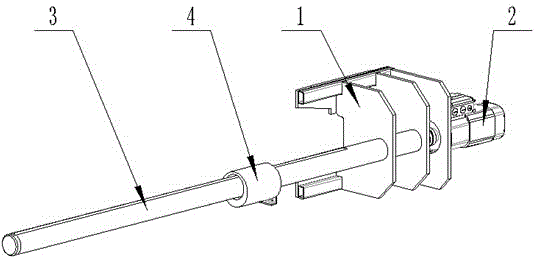
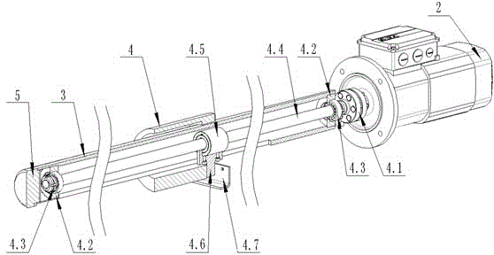
[0013] Example : a kind of pushing wire cake device, such as figure 1 , 2 As shown, it includes a bracket 1, a motor 2, a support arm 3, a lead screw 4.4, a lead screw nut 4.5 compatible with the lead screw 4.4, and a cake pusher 4. One side of the support 1 is provided with a motor 2, and the support arm 3 One end is fixed on the bracket 1, and the other end is provided with a plug 5. The support arm 3 of the cylinder is a hollow structure, and a lead screw 4.4 driven by the motor 2 through the coupling 4.1 runs through the inside, and the two ends of the lead screw 4.4 are passed through the counter. The two bearings 4.3 in the direction are installed in the bearing seat 4.2 in the support arm 3, and the leading screw nut 4.5 that is suitable is installed on the leading screw 4.4. The cake pushing head 4 is set on the outside of the support arm 3, and it is a cylindrical mating surface with the support arm 3. The support arm 3 is provided with a guide groove along the axi...


PUM


Abstract

The invention discloses a spinning cake pushing device. The spinning cake pushing device comprises a motor, a supporting arm, a lead screw which is arranged in the supporting arm in a penetration manner and driven by the motor, a lead screw nut adaptive to the lead screw, a cake pushing head which sleeves outside the supporting arm, wherein the cake pushing head is connected with the lead screw nut; the screw lead nut moves on the lead screw in a rectilinear manner to push the cake pushing head to axially move along the supporting arm. According to the spinning cake pushing device disclosed by the invention, a component for driving the cake pushing head to move is arranged inside a bracket arm, the structure is compact, the outer part is simple, the spinning cake on the supporting arm of an automatic roller can be quickly pushed to a supporting arm of a rolling vehicle; the motor drives the lead screw to move, reduction ratio characteristics of the lead screw nut are utilized, the speed reducer is not needed to be arranged, the cost is lowered and the mechanism is simplified.

Description

technical field [0001] The invention relates to the field of textile machinery, in particular to an automatic doffing machine for chemical fiber filaments. Background technique [0002] After the yarn cake (package) reaches the preset specification, the yarn cake (package) on the chuck of the winder is transferred to the support arm of the doffer, and then transferred to the subsequent package car by the doffer . After the support arm on the automatic doffer is docked with the support arm on the coil loading vehicle, the cake pushing head is driven by the chain installed on the support arm of the doffer to realize the cake pushing action. This scheme has some disadvantages: 1. The support arm must use a heterogeneous cross-section beam and reduce its cross-sectional area as much as possible to install the sprocket and chain, which is not conducive to the high rigidity requirement of the support arm under the requirement of carrying large-capacity packages; 2. It must be equ...

Claims


Application Information

Patent Timeline
Patent Type & Authority Applications(China)
IPC IPC(8): B65H67/06
Inventor 缪小方宋强王永兴王生泽杨崇昌
Owner WUXI HONGYUAN ELECTROMECHANICAL TECH
Learn More