
Method and device for enabling optical fiber preforming bar to be butted with tail handle

A technology of optical fiber preform and docking device, which is applied in the direction of manufacturing tools and glass manufacturing equipment, etc. It can solve the problems of affecting the stress of the docking part, inapplicability, and difficulty in cutting the angle of the cylinder, and achieves smooth docking parts and simple implementation methods.

Inactive Publication Date: 2015-04-29
ZHONGTIAN TECH ADVANCED MATERIALS CO LTD
View PDF6 Cites 16 Cited by
  • Summary
  • Abstract
  • Description
  • Claims
  • Application Information

AI Technical Summary

Problems solved by technology

But in practical application, it is very difficult to determine the cutting angle of the cylinder without cutting; on the other hand, the rod diameter range of the butt joint part of this patent is only 35mm~55mm, which becomes inapplicable under the trend of increasing rod diameter Furthermore, after practice, when there is a cutting angle at one end of the butt joint, although there is no air bubble remaining during the butt joint process, there are extruded protrusions and depressions, which affect the stress of the butt joint

Method used


Image

  • Method and device for enabling optical fiber preforming bar to be butted with tail handle
  • Method and device for enabling optical fiber preforming bar to be butted with tail handle
  • Method and device for enabling optical fiber preforming bar to be butted with tail handle

Examples


Embodiment 1

[0052] Example 1: Axial vapor deposition method (VAD) is used to deposit a powdery mandrel, and after dehydroxylation vitrification, a prefabricated rod with a diameter of 80 mm is formed. The preformed rod with a diameter of 80 mm is connected to a tail with a diameter of 80 mm by using the present invention. Handle for easy follow-up production.

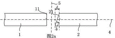
[0053] In this embodiment, θ is 5°, d=80*tan5°=7.00mm, D=2d / 3=4.67mm, according to Figure 2(a), use a cutting machine to cut the preform 1, so that the preform cut end face 11 and The axis 4 is vertical; use a cutting machine to cut the tail handle 2 so that the end face 21 forms an angle of 5° with the centerline 5 of the blowtorch.

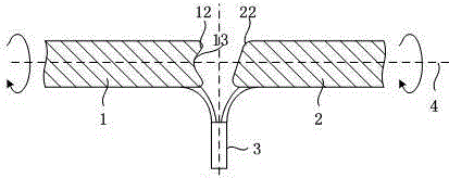
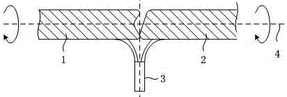
[0054] The preform rod 1 and the tail handle 2 start to rotate at a speed of 10rpm, the blowtorch 3 is ignited and burned, and the H 2 The flow rate is 300L / min, the inner O 2 Flow rate is 50 L / min, external O 2 The flow rate is 100 L / min. After burning for 8 minutes, the preform master rod 1 and ...

Embodiment 2

[0057] Embodiment 2: Axial vapor deposition method (VAD) is used to deposit a powder core rod, and a preform rod with a diameter of 50 mm is generated through dehydration vitrification, and the preform rod with a diameter of 50 mm is connected to a tail with a diameter of 50 mm by using the present invention. Handle for easy follow-up production.

[0058] In this embodiment, θ is 8°, d=50*tan8°=7.03mm, D=2d / 3=4.69mm, according to Figure 2(a), use a cutting machine to cut the preform 1, so that the preform cut end face 11 and The axis 4 is vertical; use a cutting machine to cut the tail handle 2 so that the cut end face 21 of the tail handle forms an 8° angle with the centerline 5 of the blowtorch.

[0059] The preform rod 1 and the tail handle 2 start to rotate at a speed of 10rpm, the blowtorch 3 is ignited and burned, and the H 2 Flow rate is 250L / min, inner O 2 Flow rate is 40 L / min, external O 2 The flow rate is 85 L / min. After burning for 6 minutes, the preform master ...


PUM

PropertyMeasurementUnit
diameteraaaaaaaaaa

Abstract

The invention relates to a manufacturing method and device for enabling an optical fiber preforming bar to be butted with a tail handle. The manufacturing method and device are used for enabling the optical fiber preforming bar to be butted with the tail handle. The device comprises a working table, a blowtorch, a blowtorch holder, a servo motor 1, a chuck 1, a servo motor 2, a chuck 2, a graphite roller, a graphite roller holder, a compressing cylinder, a sliding plate 1, a servo motor 3, a sliding plate 2, a servo motor 4, a sliding rail and a control panel, wherein the sliding rail is mounted at the upper part of the working table, the chuck 1 is mounted on an output shaft of the servo motor 1, and the chunk 1 is used for clamping the preforming bar; the servo motor 3 is mounted on the rear side of the sliding plate 1; the chuck 2 is mounted on an output shaft of the servo motor 2, and the chuck 2 is used for clamping the tail handle; the servo motor 4 is mounted on the rear side of the sliding plate 2; the blowtorch is mounted on the blowtorch holder; the graphite roller holder is mounted in the middle of the rear side of the working table, the graphite roller is mounted on the front side of the graphite roller holder, and the control panel is mounted on one side of the working table.

Description

technical field [0001] The patent of the present invention relates to a manufacturing method and device for butt jointing of an optical fiber preform rod and a tail handle, using the method and the device for butt jointing of an optical fiber preform rod and a tail handle. Background technique [0002] The manufacture of optical fiber and optical fiber preform is basically carried out according to the following process: the core rod in powder state is deposited by axial vapor deposition method (VAD), and the core rod in glass state is formed by dehydroxylation vitrification; then it is extended into a thinner core rod of appropriate length Rods are further coated with powdered rods around the periphery of each mandrel, and dehydroxylated and vitrified again to form large-sized preformed rods. [0003] In the manufacturing process of the optical fiber preform, the base material of the optical fiber preform needs a tail handle for support, so the butt joint between the base ma...

Claims


Application Information

Patent Timeline
Patent Type & Authority Applications(China)
IPC IPC(8): C03B37/012
Inventor 闫瑞刚沈一春缪丙华
Owner ZHONGTIAN TECH ADVANCED MATERIALS CO LTD
Learn More