Composite pile structure serving as main structure stand column and construction method thereof

A technology of main structure and composite pile, which is applied in foundation structure engineering, sheet pile wall, building, etc. It can solve the problems that the retaining wall mud will pollute the surrounding environment, the quality of the pile body is not easy to guarantee, and honeycombs and cavities are easy to appear, so as to achieve the bearing capacity Large, improved ability to resist horizontal loads, and reliable connection effects

Active Publication Date: 2015-04-29
JINAN RAILWAY TRANSPORT GRP CO LTD
View PDF6 Cites 6 Cited by
  • Summary
  • Abstract
  • Description
  • Claims
  • Application Information

AI Technical Summary

Problems solved by technology

However, there are the following problems in general bored piles: 1. The hole wall collapses during the drilling process; 2. The pile body is prone to broken piles and interlayers due to construction quality problems; 3. The diameter of the borehole shrinks due to improper construction. Phenomenon; 4. The environment in the borehole is complex, the quality of the pile body is not easy to guarantee, and honeycomb and void phenomena are prone to occur
5. The wall mud will pollute the surrounding environment; 6. The construction period is long and the construction process is complicated; 7. It cannot be used as the main force-bearing member of the main structure

Method used


Image

  • Composite pile structure serving as main structure stand column and construction method thereof
  • Composite pile structure serving as main structure stand column and construction method thereof
  • Composite pile structure serving as main structure stand column and construction method thereof

Examples


Embodiment Construction

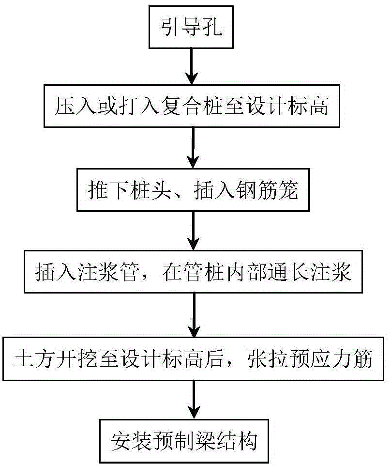
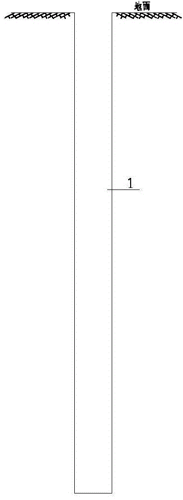
[0056] The present invention will be further described below in conjunction with the accompanying drawings and embodiments.

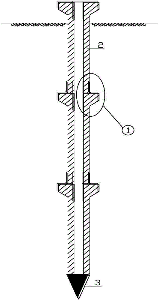
[0057] Such as Figure 2(a)-Figure 2(f) , Figure 3-Figure 14 As shown, the composite pile structure as the column of the main structure includes the segmental prefabricated pile 2 with corbels. The inner wall of the segmental precast pile 2 with corbels is provided with irregular protrusions. The shape is square on the outside and circular on the inside, the pile bottom of the segmented prefabricated pile 2 with corbels has a pile head 3, the pile top of the segmented prefabricated pile 2 with corbels has a corbel 2-1, and the pile top of the segmented precast pile 2 with corbels has a corbel 2-1, The center of the segmental prefabricated pile 2 is provided with a through hole, the through hole is provided with a steel cage 4, the through hole of the segmental prefabricated pile 2 with corbels is filled with grouting material 5, and the segmental pref...


PUM


Abstract

The invention discloses a composite pile structure serving as a main structure stand column and a construction method of the composite pile structure. The composite pile structure comprises a precast pile with brackets, wherein the precast pile is in a sectioned type, a pile head is arranged at the pile bottom of the precast pile, one bracket is arranged on the pile top of the precast pile, a through hole is formed in the center of the precast pile, a reinforcement cage is arranged in the through hole, and the through hole in the center of the precast pile is filled with grouting materials; the composite pile structure is used as the main structure stand column in the later period, the underground portion of the sectioned precast pile is wrapped by the grouting materials, a prestressed pipeline is arranged in the wall of the sectioned precast pile, prestressed reinforcing steel is arranged in the prestressed pipeline, and grouting holes are formed in the wall of the precast pile, and communicated with the through hole in the center of the precast pile. The composite pile structure has the advantages that the technological process such as mud wall protection is omitted, so that the construction cycle is shortened; the composite pile structure can serve as a stress component of a main structure, a load-bearing member does not need to be built again, the cost is saved, and pile formation quality is good; the composite pile structure can effectively solve the problem that hole collapse, hole shrinkage, pile breakage and sandwiching of a cast-in-situ bored pile happen in the construction process, and pile formation quality is guaranteed.

Description

technical field [0001] The invention belongs to the technical field of construction engineering, and in particular relates to a composite pile structure combined with a sectioned prefabricated pile with corbels and a cast-in-situ pile and a construction method thereof. Background technique [0002] With the continuous development of underground engineering, the underground excavation and reverse method has been more and more used in our country because of its short construction period, reasonable stress on the enclosure structure, and little influence of weather on construction. The combination of the support structure and the main structure in the underground excavation method has many advantages such as protecting the environment, saving social resources, and shortening the construction period. It is an effective technical means for sustainable development of urban underground space development and construction of a conservation-oriented society. , is also a new form of su...

Claims


Application Information

Patent Timeline
Patent Type & Authority Applications(China)
IPC IPC(8): E02D5/50E02D5/58E02D5/48
CPCE02D5/48E02D5/50E02D5/523E02D5/526E02D5/58E02D2250/0023E02D2250/0046E02D2250/0069E02D2300/002E02D2300/0029E02D2600/20
Inventor 王国富路林海王威汐
Owner JINAN RAILWAY TRANSPORT GRP CO LTD
Why Eureka
Try Eureka