A front-end steam turbine generator room combined with a side coal bunker and arranged at a high level

A technology of turbo generators and side coal bunkers, which is applied in the direction of machines/engines, mechanical equipment, steam engine devices, etc., and can solve problems such as cost increase

Active Publication Date: 2017-06-16
CHINA POWER ENG CONSULTING GRP CORP EAST CHINA ELECTRIC POWER DESIGN INST
View PDF8 Cites 0 Cited by
  • Summary
  • Abstract
  • Description
  • Claims
  • Application Information

AI Technical Summary

Problems solved by technology

will also lead to a substantial increase in the cost of

Method used


Image

  • A front-end steam turbine generator room combined with a side coal bunker and arranged at a high level
  • A front-end steam turbine generator room combined with a side coal bunker and arranged at a high level
  • A front-end steam turbine generator room combined with a side coal bunker and arranged at a high level

Examples


Embodiment 1

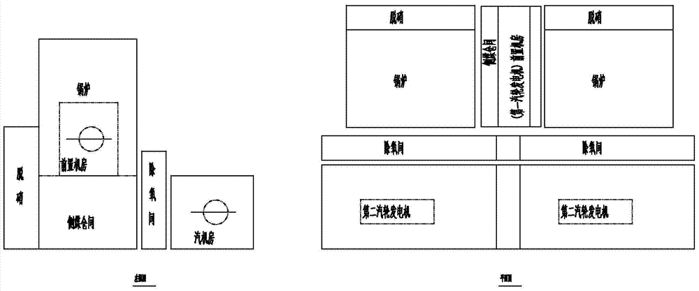
[0073] image 3 It is a structural diagram of the side coal bunker combined with a high-position front turbine generator house in embodiment 1 of the present invention.

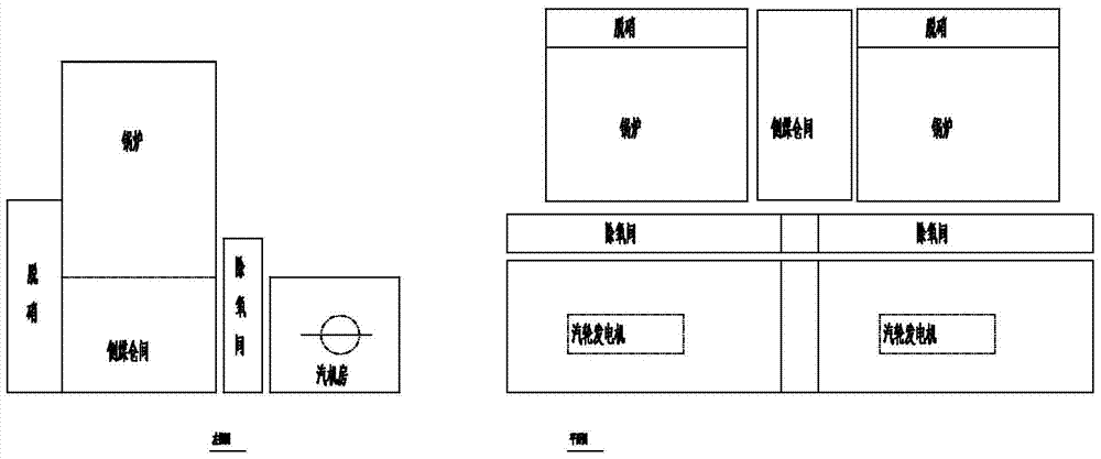
[0074] versus figure 2 Compared with the main plant of the steam turbine generator shown, the present invention arranges the front machine room of a single unit on the side coal bunker room through the side bunker frame.

[0075] The side coal bunker combined with the high-position front turbine generator house structure of the present invention includes: 2 boilers, a side coal bunker room located in the middle of the boiler, 2 deaeration rooms, a first steam turbine generator, and a second steam turbine for power generation A deaeration room is provided on the adjacent side of the proximal end of the side coal bunker, and a steam engine room is provided on the adjacent side of the deaeration room, and a second steam engine room is provided in the steam engine room. Turbo-generator, the second turbo-generator is ...

Embodiment 2

[0082] Figure 4 It is a structural diagram of the side coal bunker combined with a high-position front turbine generator house in Embodiment 2 of the present invention.

[0083] The second embodiment of the present invention is similar to the first embodiment, but the difference lies in that the front machine rooms of the two first steam turbine generators are combined and arranged above the side coal bunker located between the two boilers. The volume of the front machine room of the double unit is 72000m 3 .

[0084] The high-position front turbine generator room of this embodiment 2 can reduce the main steam pipeline site by 50%-60%, and the relative length of the main steam pipeline can reach 3 / 10, and the absolute length is ≤40m. The length of the connecting piping system can be shortened to 60m, which can save the cost of the main steam pipeline by 45%, reduce the overall cost by 18%, and increase the pipeline efficiency by more than 58%.


PUM


Abstract

The present invention provides a front steam turbine generator room combined with a side coal bunker and arranged at a high position. The machine room includes: a boiler, a side coal bunker room, an oxygen removal room, a first turbine generator, and a second turbine generator and a denitrification steel frame; wherein, a deoxygenation room is set on the side adjacent to the proximal end of the side coal bunker, a turbine room is set on the side adjacent to the deoxygenation room, and a second steam turbine is set in the turbine room generator, the second turbogenerator is provided with a high-pressure cylinder, a medium-pressure cylinder, a low-pressure cylinder, a low-pressure heater, a deaerator, a condenser, a condensate pump, and a first generator; and in the side coal bunker The side coal bunker frame is set on the side coal bunker frame, and a front machine room is set on the upper part of the side coal bunker frame, and the lower part of the side coal bunker frame is connected with the side coal bunker room, and the first steam engine room is installed in the front machine room. wheel generator. The invention reduces the occupied area of ​​the front-end unit, saves high-temperature and high-pressure pipelines, can greatly reduce the investment of high-temperature pipeline systems, and improves the normal operation efficiency.

Description

Technical field [0001] The present invention relates to the field of power plant structure, in particular to a front-mounted turbo-generator house which is combined with a side coal bunker and arranged in a high position. Background technique [0002] In conventional thermal power plants, due to the large size of the steam turbine generator and the heavier equipment, it is usually arranged on the base from the ground, and the cost of the civil structure is low. However, because the boiler is relatively tall, and the main piping interface of the main steam and reheat of the boiler is located on the upper part of the boiler, the main piping system of main steam and reheat connected between the boiler and the turbine has a longer length. The cost is high; and the piping system is longer, which will increase the flow resistance and reduce the economy of normal operation of the unit. [0003] For the transformation of the Yalin engine unit into an ultra-supercritical secondary reheat u...

Claims


Application Information

Patent Timeline
Patent Type & Authority Patents(China)
IPC IPC(8): E04H5/02F01K13/00
Inventor 冯琰磊申松林林磊施刚夜邓文祥何文珊
Owner CHINA POWER ENG CONSULTING GRP CORP EAST CHINA ELECTRIC POWER DESIGN INST
Why Eureka
Try Eureka