Regional cooling and heating system

A heating system and area technology, applied in heating systems, district heating systems, heating and ventilation control systems, etc., can solve the problems of inability to supply energy in large areas and low energy supply efficiency

Active Publication Date: 2015-04-29
江苏氿川能源科技有限公司
View PDF5 Cites 2 Cited by
  • Summary
  • Abstract
  • Description
  • Claims
  • Application Information

AI Technical Summary

Problems solved by technology

[0009] Aiming at the technical problems in the prior art that it is impossible to supply energy to a large area and the energy supply efficiency is low, the ...

Method used


Image

  • Regional cooling and heating system
  • Regional cooling and heating system
  • Regional cooling and heating system

Examples


Embodiment 1

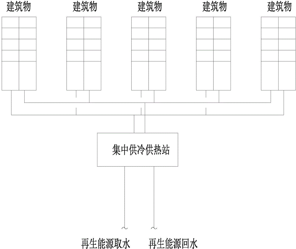
[0037] Such as Figure 4 , a district cooling and heating system, including a central cooling and heating main station 1, several cooling and heating sub-stations 2 connected to the central cooling and heating main station for cooling and heating of buildings, in order to be more To obtain heat from renewable energy sources, the centralized cooling and heating station will be built near the renewable energy sources, which can be set up in the traditional way;

[0038]A total bypass circulation pipe 5 is connected between the total outlet pipe 3 and the total return pipe 4 of the centralized cooling and heating station, and a total control valve 10 for controlling the circulation of the medium is arranged on the total bypass circulation pipe, and The detector used to detect the temperature of the medium in the total outlet pipe and the total return pipe, the detector sends the detected temperature to a controller, and the controller compares the received temperature signal with...

Embodiment 2

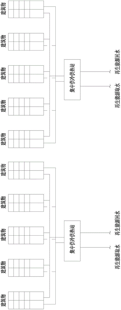
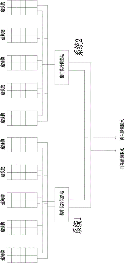
[0042] see Figure 5 , each cooling and heating sub-station can be connected in series; this avoids the defect that the heating station needs to be placed in the middle of multiple buildings in the existing traditional method, that is, the cost of the pipeline is reduced, The second is to reduce the loss of heat energy in the pipeline.

Embodiment 3

[0044] see Figure 6 , 7 , in order to improve the thermal energy efficiency of the cooling and heating sub-station 2 and reasonably recycle heat, the cooling and heating sub-station includes the first sub-heat pump unit 10, the second sub-heat pump unit 11, the second sub-heat pump unit 12, three sub-stations The heat pump units all have an input end 13 and a return end 14. The input ends of the first sub-heat pump unit, the second sub-heat pump unit, and the third sub-heat pump unit are respectively connected to the heat supply inlet pipe 6. The first sub-heat pump unit, the second sub-heat pump unit The return ends of the heat pump unit and the third sub-heat pump unit are respectively connected to the heat supply return pipe 7; in this way, the liquid medium in the central cooling and heating station can enter the three sub-heat pump units respectively through the heat supply inlet pipe for heat exchange. The final liquid medium then passes through the heat supply return ...


PUM


Abstract

The invention relates to a regional cooling and heating system comprising a main concentrate cooling and heating station and a plurality of cooling and heating substations. The cooling and heating substations are connected to the main concentrate cooling and heating station and are used for cooling and heating regionally. A main bypass circulating pipe is connected between a main discharging pipe and main returning pipe of the main concentrate cooling and heating station; a main control valve used for controlling the medium flowing and a detector used for detecting the temperature of medium in the main discharging pipe and main returning pipe are arranged on the main bypass circulating pipe; the detector transmits the detected temperature to a controller, and the controller compares a received temperature signal with a preset temperature value and controls the operation state of the main control valve according to the comparing result. The energy supply capability of the unit flow can be 11.6kW to 23.3 kW, the capability for supplying energy to substations is increased by 2 to 4 times as compared with that of the single utilization, the energy supplying radius is increased greatly by 2 to 3 kM ordinarily, and the energy supply construction area is larger than 2 million m2.

Description

technical field [0001] The invention relates to the technical problem of district energy, in particular to a district cooling and heating system. Background technique [0002] With the improvement of people's living standards and the dual effects of the demand for central heating and cooling in the south, there are more and more systems using renewable energy for district cooling and heating. According to the technical characteristics of renewable energy, its energy supply radius is generally within the range of 1kM. After exceeding a certain range, its economy will be greatly reduced due to the increase of power consumption and heat loss of the delivery pump. At present, the more common forms of district cooling and heating systems using renewable energy are as follows: [0003] Traditional way 1: [0004] Such as figure 1 , this system is the most common system. Due to the limitation of the temperature difference in the use of renewable energy, the temperature differenc...

Claims


Application Information

Patent Timeline
IPC IPC(8): F24D10/00F24D19/10F24F3/00F24F11/02
CPCY02B30/17
Inventor 欧阳杰南韦伟吴斯奇宋洋王凭苏翔
Owner 江苏氿川能源科技有限公司
Why Eureka
Try Eureka