A heat pump driven internal cooling solution dehumidification fresh air unit

A solution dehumidification, heat pump driven technology, applied in space heating and ventilation, space heating and ventilation details, household heating and other directions, can solve the problem of lack of heat pump driven solution dehumidification device, solution concentration reduction, etc., to meet the improvement demand Inconsistencies, full utilization, effects of improving energy efficiency levels

Active Publication Date: 2017-07-18
TSINGHUA UNIV
View PDF3 Cites 0 Cited by
  • Summary
  • Abstract
  • Description
  • Claims
  • Application Information

AI Technical Summary

Problems solved by technology

However, the function of the regeneration module itself is to increase the concentration of the solution and realize the concentrated regeneration of the solution, while replenishing water directly leads to a decrease in the concentration of the solution. There is a significant contradiction between the two
From the perspective of solution regeneration, the heat on the side of the condenser can be effectively utilized, and the above-mentioned schemes of setting up an auxiliary condenser to discharge the heat of condensation have failed to make full use of the heat on the side of the condenser to regenerate the solution
[0005] Therefore, from the perspective of the prior art, there is still a lack of a heat pump-driven solution dehumidification device that can use all the heat on the condenser side for solution regeneration

Method used


Image

  • A heat pump driven internal cooling solution dehumidification fresh air unit
  • A heat pump driven internal cooling solution dehumidification fresh air unit

Examples


Embodiment 1

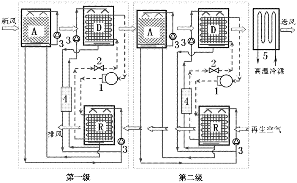
[0017] like figure 1 As shown, the fresh air unit of this embodiment includes fresh air processing units arranged in multiple stages, and each fresh air processing unit includes an internal cooling type solution dehumidifier D, an internal heating type solution regenerator R, and an auxiliary adiabatic type solution dehumidifier A device A, a compressor 1 and an expansion valve 2, wherein, an evaporator is built in the internal cooling type solution dehumidifier D, a condenser is built in the internal heating type solution regenerator R, and the compressor 1, the internal heating type solution regenerator R The condenser in D, the expansion valve 2 and the evaporator in the internal cooling solution dehumidifier D are connected in sequence to form a heat pump cycle. The auxiliary adiabatic solution dehumidifier A is connected with a solution circulation pump 3 to form a solution circulation loop in the dehumidifier; the internal heating solution regenerator R passes through a ...

Embodiment 2

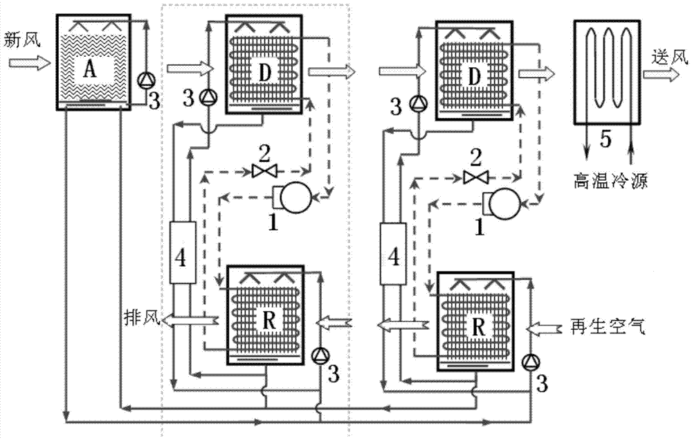
[0028] like figure 2 As shown, the difference between this embodiment and Embodiment 1 is that no auxiliary adiabatic solution dehumidifier A is installed in the fresh air treatment units at all levels, and only one auxiliary adiabatic solution dehumidifier is installed in the whole fresh air treatment unit. A device A, which is set in front of the internal cooling solution dehumidifier D of the first-stage fresh air processing unit, and the auxiliary adiabatic solution dehumidifier A is connected with a solution circulation pump 5 to form a solution circulation loop in the dehumidifier to assist the adiabatic solution dehumidification The device A is connected with the internal heating solution regenerator R of the fresh air treatment units at all levels to form a solution circulation loop.

[0029] The working principle of the fresh air treatment unit in this embodiment (the fresh air treatment unit including two-stage fresh air treatment unit I is used as an example to ill...


PUM


Abstract

The invention relates to an inner-cooling type solution desiccant fresh air unit driven by a heat pump. The inner-cooling type solution desiccant fresh air unit comprises fresh air treatment units in multiple stages, the fresh air treatment unit of each stage comprises an inner-cooling type solution dehumidifier, an inner-heating type solution regenerator, an auxiliary heat-insulation solution dehumidifier, a compressor and an expansion valve. An evaporator is embedded in the inner-cooling type solution dehumidifier, a condenser is embedded in the inner-heating type solution regenerator, the compressor, the condenser in the inner-heating type solution regenerator, the expansion valve and the evaporator in the inner-cooling type solution dehumidifier are sequentially connected to form a heat pump circulating loop, the auxiliary heat-insulation type solution dehumidifier is connected with a solution circulating pump to form an inside-dehumidifier solution circulating loop, the inner-heating type solution regenerator is connected with the inner-cooling type solution dehumidifier and the auxiliary heat-insulation type solution dehumidifier through a solution circulating pump to form a solution circulating loop, and a solution-solution heat exchanger is arranged on the solution circulating loop between the inner-cooling type solution dehumidifier and the inner-heating type solution regenerator.

Description

technical field [0001] The invention relates to a fresh air unit, in particular to a heat pump driven internal cooling solution dehumidification fresh air unit. Background technique [0002] The main task of the civil building air conditioning system is to meet the requirements of suitable indoor temperature and humidity parameters, and the air dehumidification process is an important part of it. Most of the existing dehumidification methods are based on condensation dehumidification, that is, low-temperature cold water, refrigerants and other refrigerants are used to cool the air below the dew point temperature, so that the moisture in the air condenses to complete the dehumidification process. Due to the low temperature of the cold source required (lower than the dew point temperature of the air), the evaporation temperature of the refrigerator is reduced, which seriously affects the coefficient of performance of the refrigerator. In addition, the traditional condensing d...

Claims


Application Information

Patent Timeline
Patent Type & Authority Patents(China)
IPC IPC(8): F24F5/00F24F13/30
CPCF24F3/14F24F5/001F24F13/30F24F2003/1458
Inventor 刘晓华张涛江亿
Owner TSINGHUA UNIV
Why Eureka
Try Eureka