Sensible heat storage type cavity concentrating and absorbing heat solar heat collection device and method

A solar heat collector and heat storage technology, which is applied in solar thermal devices, solar heat collectors, solar heat collectors using working fluids, etc., can solve the problem of long heat transfer loops, low overall system efficiency, resistance and heat loss and other problems, to achieve the effect of improving utilization rate, compact structure, and solving discontinuous irradiation

Active Publication Date: 2016-03-09
ZHEJIANG UNIV
View PDF7 Cites 0 Cited by
  • Summary
  • Abstract
  • Description
  • Claims
  • Application Information

AI Technical Summary

Problems solved by technology

However, for the existing solar combined cycle thermal power generation system, due to the influence of the fluctuation characteristics of solar radiation, the addition of solar collectors not only increases the difficulty of control and operation of coal-fired units, but also the heat load of the relevant heating surface fluctuates greatly , the changes are complicated, and the stability and safety of the boiler operation will decrease accordingly.
At present, the more effective way to solve this kind of problem is to equip a high-temperature molten salt heat storage system similar to solar trough power plants, but in this system, the heat collection device and heat storage device (molten salt tank) are separated. Heat transfer needs to be achieved by high-temperature heat transfer medium flowing in complex pipelines. The heat transfer circuit is long, the resistance and heat loss are serious, and the unit cost is caused by factors such as the large amount of heat storage tank materials and molten salt used, and the maintenance of high temperature. Relatively high operating costs and low overall system efficiency

Method used


Image

  • Sensible heat storage type cavity concentrating and absorbing heat solar heat collection device and method
  • Sensible heat storage type cavity concentrating and absorbing heat solar heat collection device and method
  • Sensible heat storage type cavity concentrating and absorbing heat solar heat collection device and method

Examples


Embodiment Construction

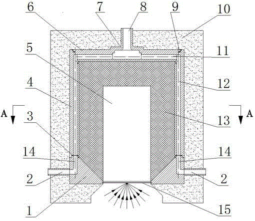
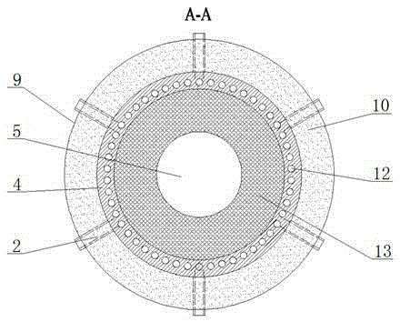
[0027] Such as Figure 1-5 As shown, the sensible heat storage cavity concentrating and heat absorbing solar heat collection device includes an inlet annular shunt cavity 1, a first sealing gasket 3, a sleeve heat exchanger 4, a heat absorption cavity 5, an outlet confluence cavity 6, a second Two sealing gaskets 9, insulation layer 10, heat storage body 13) lens 15;

[0028] The body of the heat collecting device is provided with a heat absorbing chamber 5, a heat accumulator 13, and a sleeve heat exchanger 4 sequentially from the inside to the outside, and a lens 15 is installed at the mouth of the heat absorbing chamber 5; The inner wall of the cylindrical heat exchanger 4 is closely attached;

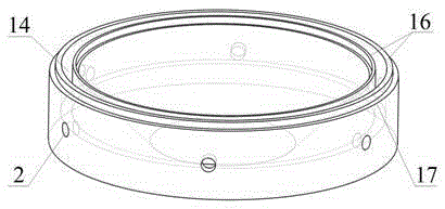
[0029] The inlet annular distribution chamber 1 includes the cold fluid inlet flow channel 2, the inlet annular distribution chamber flow channel 14, the inlet annular distribution chamber sealing groove 16, and the inlet annular distribution chamber upper edge 17;

[0030] A plur...


PUM


Abstract

The invention discloses a sensible heat storing type cavity light collecting and heat absorbing type solar heat collecting device. The device comprises an inlet annular distribution cavity, a first sealing gasket, a sleeve type heat exchanger, a heat absorbing cavity, an outlet flow collecting cavity, a second sealing gasket, a heat preserving layer, a heat storing body and a lens; the heat absorbing cavity, the heat storing body and the sleeve type heat exchanger are arranged at the heat collecting device from inside to outside in a sequence; the lens is arranged at an opening of the heat absorbing cavity; the outer wall of the heat storing body is closely clung to the inner wall of the sleeve type heat exchanger; the inlet annular distributing cavity comprises a cold liquid inlet runner, an inlet annular distributing cavity runner, an inlet annular distribution cavity sealing conduit and an inlet annular distribution cavity upper edge; the sleeve type heat exchanger comprises a heat exchanger runner, a heat exchanger lower edge, a heat exchanger lower sealing conduit, a first heat exchanger upper sealing conduit, a second heat exchanger upper sealing conduit and a heat exchanger upper edge. According to the device, the heat storing body is used as a solar cavity absorber; the system is compact in structure; the problem of instable solar heat output can be effectively solved.

Description

technical field [0001] The invention relates to a sensible heat storage type cavity concentrating and heat absorbing solar heat collecting device and method, belonging to the technical field of solar heat utilization. Background technique [0002] At present, the reserves of traditional energy are decreasing day by day, and the problem of environmental pollution is increasing day by day. The utilization of solar energy heat has received more and more attention, and has become an important direction of my country's current energy development. Among them, the combined cycle thermal power generation technology of solar energy and traditional fossil energy or the use of solar energy to directly supply the heat required by the water heating network are of great significance to alleviate the shortage of fossil energy in my country and achieve energy conservation and emission reduction. [0003] Domestic and foreign research on combined cycle thermal power generation technology of ...

Claims


Application Information

Patent Timeline
Patent Type & Authority Patents(China)
IPC IPC(8): F24J2/24F24J2/34F24J2/46F24S10/70
CPCY02E10/44
Inventor 王宇飞张良俞自涛范利武华蒙王涛胡亚才洪荣华
Owner ZHEJIANG UNIV
Why Eureka
Try Eureka