
Thermosiphon Oil Cooling System

An oil cooling system and thermosiphon technology, applied in refrigerators, refrigeration components, refrigeration and liquefaction, etc., can solve the problems of increasing the complexity of the structure of the thermosiphon liquid receiver 1, increasing the process complexity of the thermosiphon oil cooler, and excessive loss To solve problems such as coldness, achieve the effect of simple thermosiphon oil cooling process, simple structure, and effective utilization

Active Publication Date: 2016-09-14
SINOHYDRO BUREAU 8 CO LTD
View PDF3 Cites 0 Cited by
  • Summary
  • Abstract
  • Description
  • Claims
  • Application Information

AI Technical Summary

Problems solved by technology

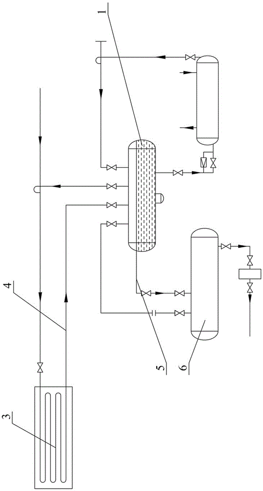
like figure 1 As shown, it includes a thermosiphon accumulator 1, a condenser 3 and a high-pressure accumulator 6, and the liquid outlet of the condenser 3 and the liquid inlet of the thermosiphon accumulator 1 are communicated through a condenser liquid outlet pipe 4, The overflow port of the thermosiphon liquid accumulator 1 and the liquid inlet of the high-pressure liquid accumulator 6 communicate through the thermosiphon liquid accumulator overflow pipe 5. The shortcoming of this thermosiphon oil cooling system is that the liquid refrigerant condensed by the condenser It has a certain degree of subcooling, which is offset by the high temperature saturated return air from the thermosiphon oil cooler, which loses the degree of supercooling and causes a waste of energy
[0003] Many technicians try to solve the technical problem of subcooling loss, but they all start from the internal structure of the thermosiphon liquid reservoir 1, which inevitably increases the complexity of the structure of the thermosiphon liquid reservoir 1, and the corresponding Increased complexity of thermosiphon oil cooler process

Method used


Image

  • Thermosiphon Oil Cooling System
  • Thermosiphon Oil Cooling System
  • Thermosiphon Oil Cooling System

Examples


Embodiment approach

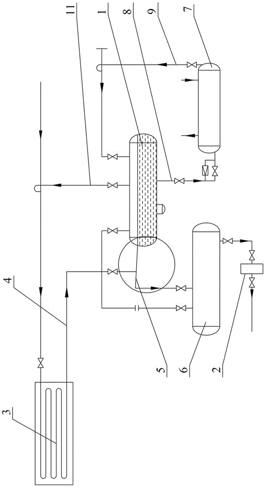
[0028] figure 2 and image 3 The first embodiment of the thermosiphon oil cooling system of the present invention is shown, including a thermosiphon liquid reservoir 1, a return gas pipeline 11, a regulating station 2, a condenser 3, a condenser liquid outlet pipe 4, and a thermosiphon liquid reservoir The overflow pipe 5, the high-pressure liquid reservoir 6, the thermosiphon oil cooler 7, the liquid outlet pipe 8 of the thermosiphon liquid reservoir, the air return pipe 9 of the oil cooler, and the high-pressure liquid reservoir 6 communicate with the regulating station 2 through pipelines. The thermosiphon liquid reservoir 1 is provided with an air return port, an overflow port, an air outlet and a liquid outlet, wherein the air return port is connected with the thermosiphon oil cooler 7 through the oil cooler return air pipe 9, and the overflow port and the high pressure The liquid reservoir 6 is communicated with the overflow pipe 5 of the thermosiphon liquid reservoir,...

Embodiment 2

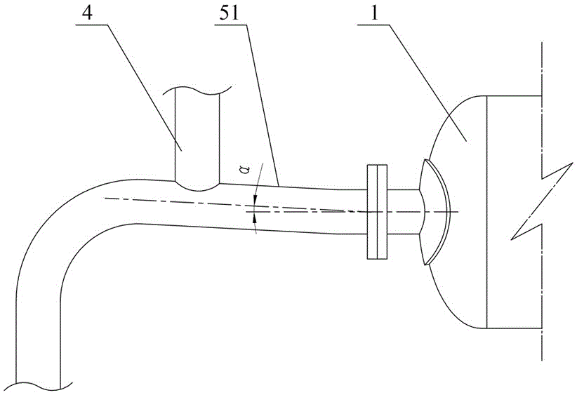
[0038] Figure 4The second embodiment of the thermosiphon oil cooling system of the present invention is shown. The difference from the first embodiment is that the heat insulation pipe section 51 includes a first reducing pipe 511, a horizontal pipe 512 and a second reducing pipe 513, The horizontal pipe 512 connects the large end of the first variable diameter tube 511 and the large end of the second variable diameter tube 513, the small end of the first variable diameter tube 511 is close to the overflow port of the thermosiphon liquid reservoir 1, and the second variable diameter tube The small head end of the pipe 513 is close to the high-pressure liquid reservoir 6 , and the outlet pipe 4 of the condenser is connected to the horizontal pipe 512 and is close to the second reducing pipe 513 . The first reducing tube 511 and the second reducing tube 513 may be concentric or eccentric reducing tubes. The lowest point of the inner wall of the small head end of the second var...

Embodiment 3

[0041] Figure 5 The third embodiment of the thermosiphon oil cooling system of the present invention is shown. The difference from the second embodiment is that the heat insulation pipe section 51 includes a second reducing pipe 513 and a horizontal pipe 512, and one end of the horizontal pipe 512 is connected to the heat The overflow port of the siphon liquid reservoir 1 is connected, and the other end is connected with the big end of the second variable diameter pipe 513, the small end of the second variable diameter pipe 513 is close to the high pressure liquid reservoir 6, and the condenser liquid outlet pipe 4 is connected to the horizontal The tube 512 is connected and is close to the second reducing tube 513 .


PUM


Abstract

The invention discloses a thermosiphon oil cooling system, which comprises a thermosiphon liquid storage device, a condenser and a high-pressure liquid storage device, and also includes a liquid outlet pipe of the condenser and an overflow pipe of the thermosiphon liquid storage device. The thermosiphon liquid storage device The overflow port of the condenser and the high-pressure liquid reservoir are connected through the overflow pipe of the thermosiphon liquid reservoir. One end of the condenser liquid outlet pipe is connected to the liquid outlet of the condenser, and the other end is connected to the overflow pipe of the thermosiphon liquid reservoir. Tube. The thermal siphon oil cooling system of the present invention has the advantages of simple structure, convenient modification, safety and reliability, and energy saving.

Description

technical field [0001] The invention relates to a refrigeration system, in particular to a thermosiphon oil cooling system. Background technique [0002] At present, refrigeration systems are generally divided into thermosiphon oil cooling and water cooling. Water cooling is an energy-saving oil cooling method. Its disadvantages are that it consumes water resources, and the heat exchanger is prone to fouling that affects heat transfer. Thermosyphon oil cooling uses the pressure difference formed by the different densities of liquid and gas to circulate, without pumps and other conveying equipment. Compared with water cooling, thermosiphon oil cooling can save water source, and can avoid fouling in the heat exchanger and affect heat transfer, so it is widely used. like figure 1 As shown, it includes a thermosiphon accumulator 1, a condenser 3 and a high-pressure accumulator 6, and the liquid outlet of the condenser 3 and the liquid inlet of the thermosiphon accumulator 1 ar...

Claims


Application Information

Patent Timeline
Patent Type & Authority Patents(China)
IPC IPC(8): F25B1/00F25B43/00
CPCF25B43/006F25B41/40
Inventor 陈笠曾凡杜韩可林刘菊红李跃兴涂怀健于永军张祖义
Owner SINOHYDRO BUREAU 8 CO LTD
Learn More