
Middle and small span bridge deflection measuring device

A bridge deflection and measuring device technology, applied in the direction of mechanical solid deformation measurement, etc., can solve the problems of inability to continuously measure multiple sections, the ruler cannot stand, and the test cannot be carried out, and achieves easy popularization, easy installation and implementation, and simple structure Effect

Inactive Publication Date: 2015-04-29
CHANGAN UNIV
View PDF7 Cites 15 Cited by
  • Summary
  • Abstract
  • Description
  • Claims
  • Application Information

AI Technical Summary

Problems solved by technology

When this method is used for bridge detection, it is necessary to manually hold the scale, which will produce unavoidable human errors, and is often subject to loading vehicles (a test vehicle with a certain weight needs to be parked on the bridge during the static load test, and it is loaded with the weight of the vehicle and The influence of testing the deflection of the main beam), the prism or the ruler cannot stand on the test section, or the line of sight of the total station or laser deflection meter is directly blocked by the arrangement of the loading vehicle, so the test cannot be carried out, and this test method can only measure a single Section, cannot measure multiple sections continuously

Method used


Image

  • Middle and small span bridge deflection measuring device
  • Middle and small span bridge deflection measuring device
  • Middle and small span bridge deflection measuring device

Examples


Embodiment Construction

[0034] The present invention will be further described below in conjunction with specific embodiments. The exemplary embodiments and descriptions of the present invention are used to explain the present invention, but not as a limitation to the present invention.

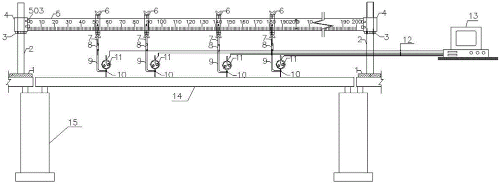
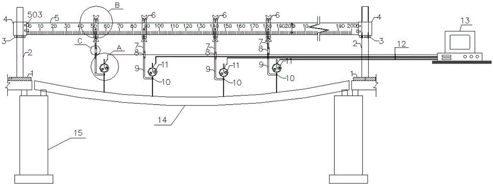
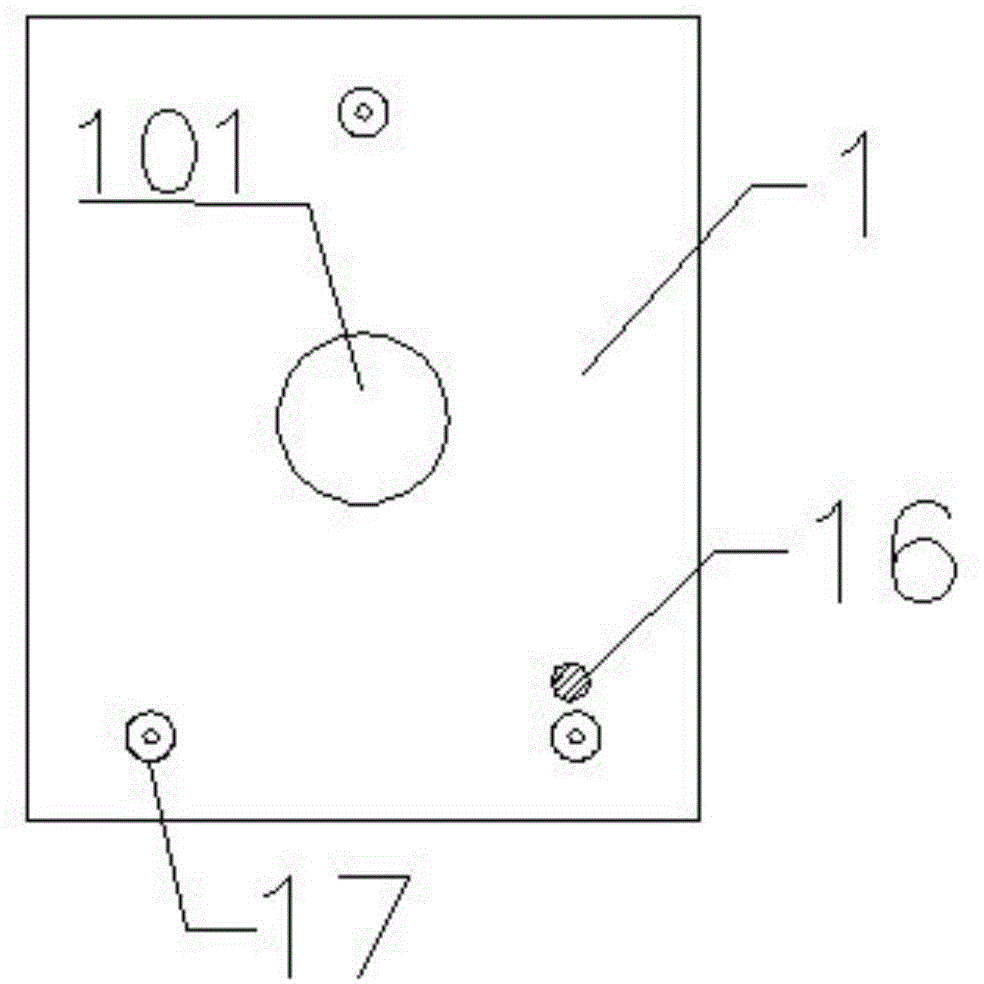
[0035] like figure 1 , figure 2 , Image 6 The device for measuring the deflection of a bridge with a small and medium span is installed on the main girder 14 to be tested, and there is a pier 15 under the main girder 14 to be tested, including a column support device, a rigid guide beam 5, an electromechanical dial indicator 11, and a table frame Connect the support device and the data acquisition system 13, and set a column support device at the beginning and end of the bridge span of the main girder 14 to be tested. 3 and the cube connection device 4 on the upper part of the height adjustment nut 3. The two ends of the rigid guide beam 5 are connected with the cube connection device 4 respectively. , the elec...


PUM


Abstract

The invention discloses a middle and small span bridge deflection measuring device. The device is installed on a main beam to be measured and comprises stand column supporting devices, a rigid guide beam, an electromechanical dial indicator, a dial indicator stand connecting and supporting device and a data acquiring system, wherein the starting point and end point of a bridge span of the main beam to be measured are each provided with one stand column supporting device, each stand column supporting devices is composed of a supporting base, a threaded stand column above the supporting base, a height adjusting nut arranged on the threaded stand column, and a cuboid connecting device above the height adjusting nut, the two ends of the rigid guide beam are connected with the cuboid connecting devices respectively, the outer side of the rigid guide beam is engraved with scale markers, a steel hoop is fixedly installed on the rigid guide beam, the electromechanical dial indicator is connected with the steel hoop through the dial indicator stand connecting and supporting device, the bottom of the dial indicator stand connecting and supporting device maintains contact with the main beam to be measured, and the electromechanical dial indicator is connected with the data acquiring system through a data line. When the device is used for measuring the deflection of middle and small span bridges, accurate positioning of measurement points and quick acquisition of data can be achieved.

Description

technical field [0001] The invention relates to a deflection measuring device for small and medium span bridges, which can be widely used in many fields such as real bridge detection and test research. Background technique [0002] Regular inspection of the bridge structure is very important. The current condition of the bridge can be evaluated through bridge inspection, which provides a reliable guarantee for later operation and driving safety. So far, the measurement of vertical displacement (deflection) in bridge detection mainly adopts the above two methods, 1. The method of erecting displacement sensors 2. The method of optical instruments. However, it is often interfered by external and human factors, which makes the data unable to be measured accurately. [0003] 1. Bracket erection displacement sensor method [0004] Bracket erection displacement sensor method: During bridge inspection, a bracket is erected between the bottom of the main girder and the ground, and ...

Claims


Application Information

Patent Timeline
Patent Type & Authority Applications(China)
IPC IPC(8): G01B5/30
Inventor 周敉张玥樊卫江刘元任伟
Owner CHANGAN UNIV
Learn More