Measuring device for optically scanning an environment

A measurement equipment and optical ground technology, applied in the field of laser scanners, can solve the problems of expensive structure, extra power source for cameras, and complicated operation of measurement equipment, and achieve the effect of simple structure and compact construction

Active Publication Date: 2015-04-29
HEXAGON TECH CENT GMBH
View PDF7 Cites 2 Cited by
  • Summary
  • Abstract
  • Description
  • Claims
  • Application Information

AI Technical Summary

Problems solved by technology

The disadvantage of measuring devices implemented in this way is that they are often complex to operate
Moreover, the construction of such a measuring device (especially for the optics used) is expensive
Moreover, the necessary images recorded by the camera must be processed by corresponding software, and the camera requires an additional power source

Method used


Image

  • Measuring device for optically scanning an environment
  • Measuring device for optically scanning an environment
  • Measuring device for optically scanning an environment

Examples


Embodiment Construction

[0058] figure 1 A measuring device according to the prior art is shown, as already described in detail above.

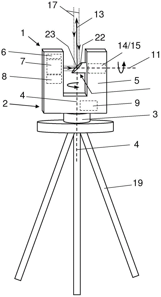
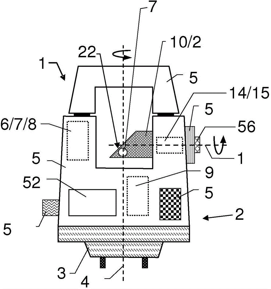
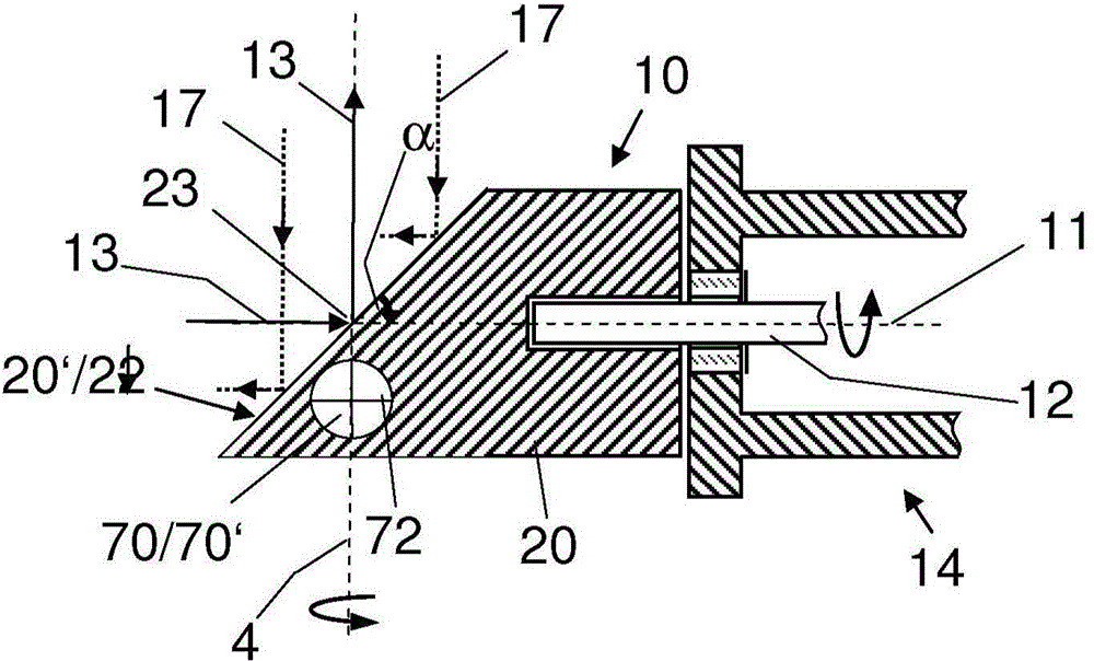
[0059] figure 2 A first embodiment of a measuring device 1 according to the present invention is shown, which has a rotating unit 10 implemented according to the present invention, which is shown in detail in image 3 . The measuring device 1 is usually equipped with a measuring head 2, and the housing 5 of the measuring head 2 is mounted on the base 3 in a manner capable of rotating about the base axis 4. In the housing 5, there are provided: a radiation source 6 for generating a transmission beam 13 and a receiving sensor 8 for detecting the captured reflected radiation 17, which is preferably reflected at the target object; and an optical component 7, It is used for beam guidance and alignment of the transmitted optical radiation 13 and the reflected radiation 17. The rotating unit 10 has a beam deflecting element 22 for deflecting the transmission beam 13 in an ai...


PUM


Abstract

The invention relates to a measuring device (1), in particular a laser scanner for optically scanning and measuring an environment. The measuring device (1) comprises a rotatably mounted measuring head (2) and a rotation unit (10) mounted therein and having a rotatably mounted rotation body (20), wherein a targeting element (70) for sighting a target point is integrated into the rotation body (20), said targeting element comprising an opening (70′) passing through the rotation body (20).

Description

Technical field [0001] The invention relates to measuring equipment, especially laser scanners, for optically scanning or measuring environments. The measuring device includes a rotating unit, the rotating unit has a deflection element and a rotating body, the deflection element is used for deflecting the transmission beam and the receiving beam. Background technique [0002] Measuring devices or scanners of the type mentioned in the preamble are designed to measure spatial regions and / or objects in three dimensions. Typical applications include, for example, measurement of interiors (such as churches and industrial buildings), large objects (such as buildings or airplanes), or public measurement of accident locations. [0003] In order to measure these objects, a laser scanner is used to scan a predetermined volume of space with a laser beam, and the laser light reflected from the object is detected. For each point, the direction for the emitted laser beam and the detected Angle...

Claims


Application Information

Patent Timeline
Patent Type & Authority Applications(China)
IPC IPC(8): G01C11/00G01S17/86
CPCG01C15/002G01S7/4812G01S7/4817G01S7/4972G01S17/06G01S17/86G01S17/42
Inventor S·贝斯特勒J·舍加
Owner HEXAGON TECH CENT GMBH
Why Eureka
Try Eureka