Loading force direction self-balanced loading device and force direction self-controlled numerical control knife rest static rigidity test platform

A technology of loading device and test platform, which is applied in the testing of mechanical components, testing of machine/structural components, measuring devices, etc., can solve the problem of force loading direction deviation, difficult to control the position of force loading point, and tool holder static stiffness test process. Insufficient specification and other problems to achieve the effect of ensuring verticality, preventing offset and change

Active Publication Date: 2015-04-29
SOUTHEAST UNIV
View PDF9 Cites 20 Cited by
  • Summary
  • Abstract
  • Description
  • Claims
  • Application Information

AI Technical Summary

Problems solved by technology

[0004] Purpose of the invention: In order to solve the technical problems that the static stiffness test process of the tool holder is no

Method used


Image

  • Loading force direction self-balanced loading device and force direction self-controlled numerical control knife rest static rigidity test platform
  • Loading force direction self-balanced loading device and force direction self-controlled numerical control knife rest static rigidity test platform
  • Loading force direction self-balanced loading device and force direction self-controlled numerical control knife rest static rigidity test platform

Examples


Embodiment

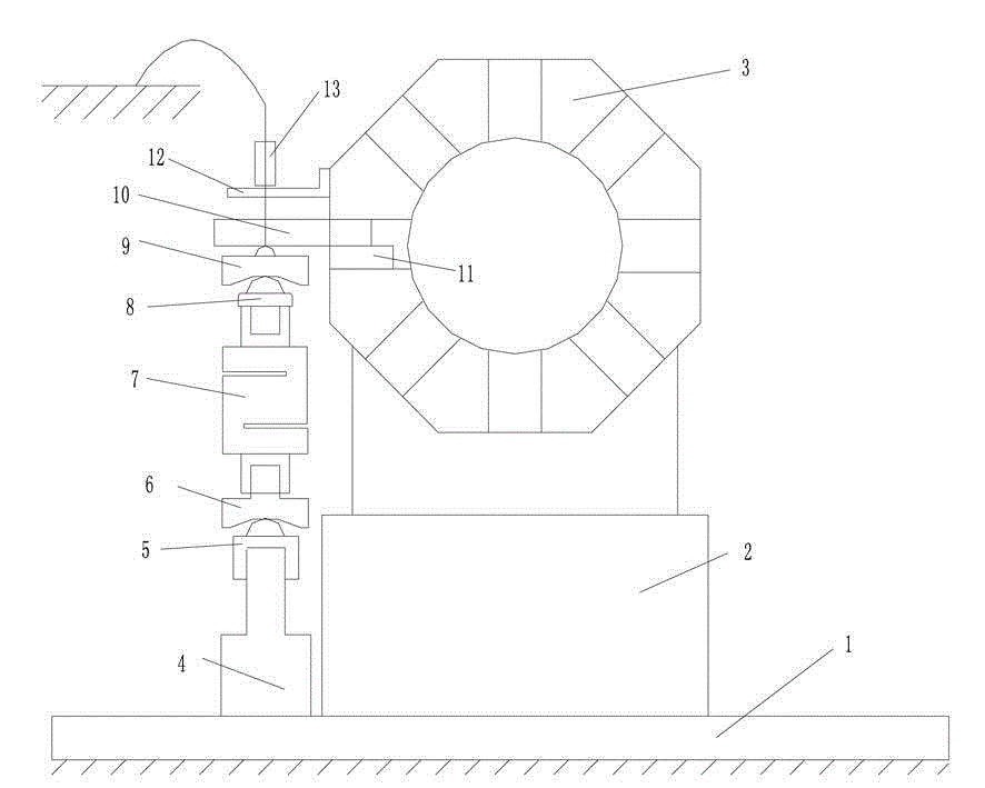
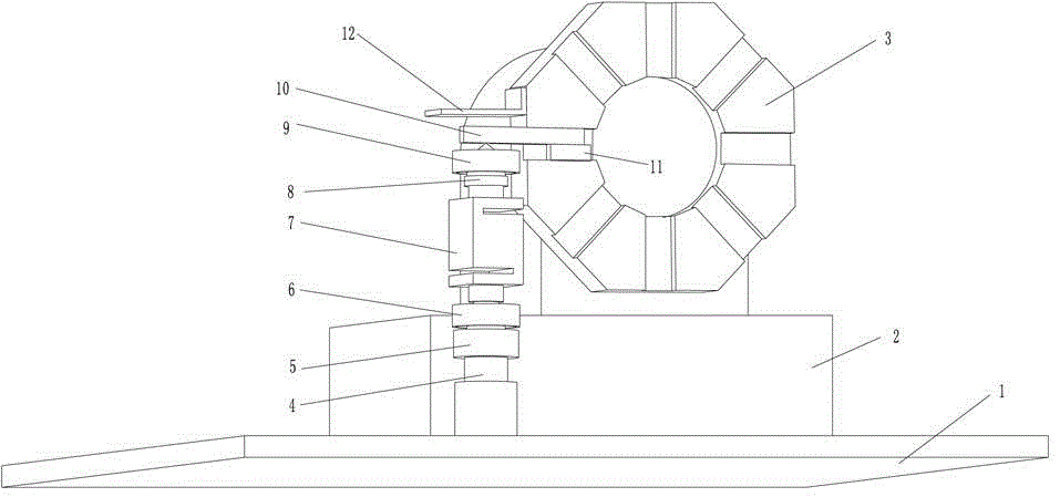
[0037] The static stiffness testing device of the tool holder of the present embodiment to ensure that the load force is applied to the point and direction is as follows: figure 1 with figure 2 As shown, the CNC tool post 3 is fixed on the rigid tool post fixed chassis 2, and the tool post fixed chassis 2 is fixedly connected to the test bench 1 through a clamp. The knife bar 9 is clamped and fixed on a certain station on the numerically controlled tool rest 3 by the knife pressing block 11 . Due to the problem that it is easy to slip when directly collecting the displacement of the measuring point of the cutter head of the tool holder, a cutter head receiving plate 12 is designed and installed on the cutter head by screws or other methods as a displacement test point. The eddy current sensor probe 13 in the displacement testing device is fixed by the universal magnetic gauge base, and the reference of the magnetic base is the ground.

[0038] The jack 4 is fixed on the te...


PUM


Abstract

The invention discloses a loading force direction self-balanced loading device and a force direction self-controlled numerical control knife rest static rigidity test platform, belonging to the field of test of basic performance parameters of functional parts of numerical control machine tools. The loading device is fixedly arranged on a test bed rack, and the loading force direction is always perpendicular to a cutter bar by virtue of self-balance of a ball pair and does not deviate; single-point centralized loading of the force is realized, and the accuracy of the loading position is guaranteed; according to the test device, the ground is taken as the reference, a designed cutter head bearing plate is selected as a measuring point, the measuring point and the load point are positioned on the same vertical line, and the test error caused by deformation of other functional parts of the machine tool is overcome. The device and the test scheme have the greatest advantages that the accuracy of the direction and position of the loading force is guaranteed. The loading device also can be applied to the static rigidity test of other functional parts of the machine tool and other mechanical products.

Description

technical field [0001] The invention relates to a static load loading device and a stiffness testing system for mechanical structural components, in particular to a loading device with self-balancing load force direction and a static stiffness test platform for CNC tool holders with self-control force direction, which belongs to the basic performance of functional components of machine tools Parametric testing technology field. Background technique [0002] CNC tool post is one of the core functional components of CNC lathes and turning-milling compound machining centers, which can realize tool installation, clamping and tool changing in turning, boring, milling, drilling and other processing technologies. The cutting load resistance performance of the tool post, that is, the static stiffness, largely affects and determines the machining accuracy, precision retention capability of the CNC machine tool, and the matching characteristics of the stiffness of the machine tool and...

Claims


Application Information

Patent Timeline
IPC IPC(8): G01M13/00
Inventor 孙蓓蓓刘鑫陈南张建润卢熹
Owner SOUTHEAST UNIV
Why Eureka
Try Eureka