
Ultra-high temperature heat-insulating property testing device and method

A test device and ultra-high temperature technology, applied in the field of ultra-high temperature thermal insulation performance test devices, can solve the problems of high construction and use costs, sample airflow erosion, long test cycle and other problems, and achieve convenient operation, rapid temperature rise and fall, and shortened test effect of cycle

Active Publication Date: 2015-04-29
CHINA BUILDING MATERIALS ACAD
View PDF5 Cites 18 Cited by
  • Summary
  • Abstract
  • Description
  • Claims
  • Application Information

AI Technical Summary

Problems solved by technology

Moreover, because the flame directly heats the sample, it will cause airflow erosion to the sample.
The fourth category is the wind tunnel test device. This type of device can simulate the actual working conditions of high-speed aircraft such as missiles to the greatest extent. However, the cost of construction and use of this type of equipment is extremely high, and the test cycle is long. It is suitable for the simulation test of the whole machine and is not suitable for conventional Research on the properties of materials
[0003] To sum up, there are many problems in the existing technology, and there is no closed ultra-high temperature (above 2000°C) heat insulation performance testing device

Method used


Image

  • Ultra-high temperature heat-insulating property testing device and method
  • Ultra-high temperature heat-insulating property testing device and method

Examples


Embodiment Construction

[0034] The present invention will be described in further detail below in conjunction with the accompanying drawings and specific embodiments, but not as a limitation of the present invention. In the following description, different "one embodiment" or "embodiment" do not necessarily refer to the same embodiment. Furthermore, the particular features, structures, or characteristics of one or more embodiments may be combined in any suitable manner. Existing technologies can be adopted for the parts not mentioned in the embodiments.

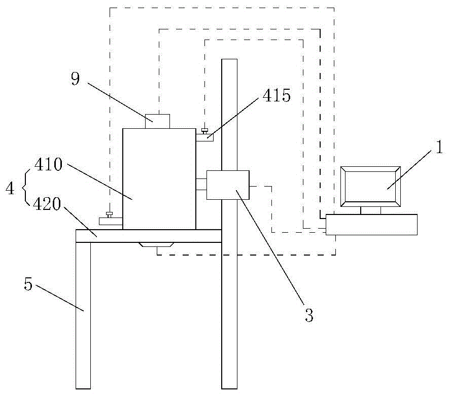
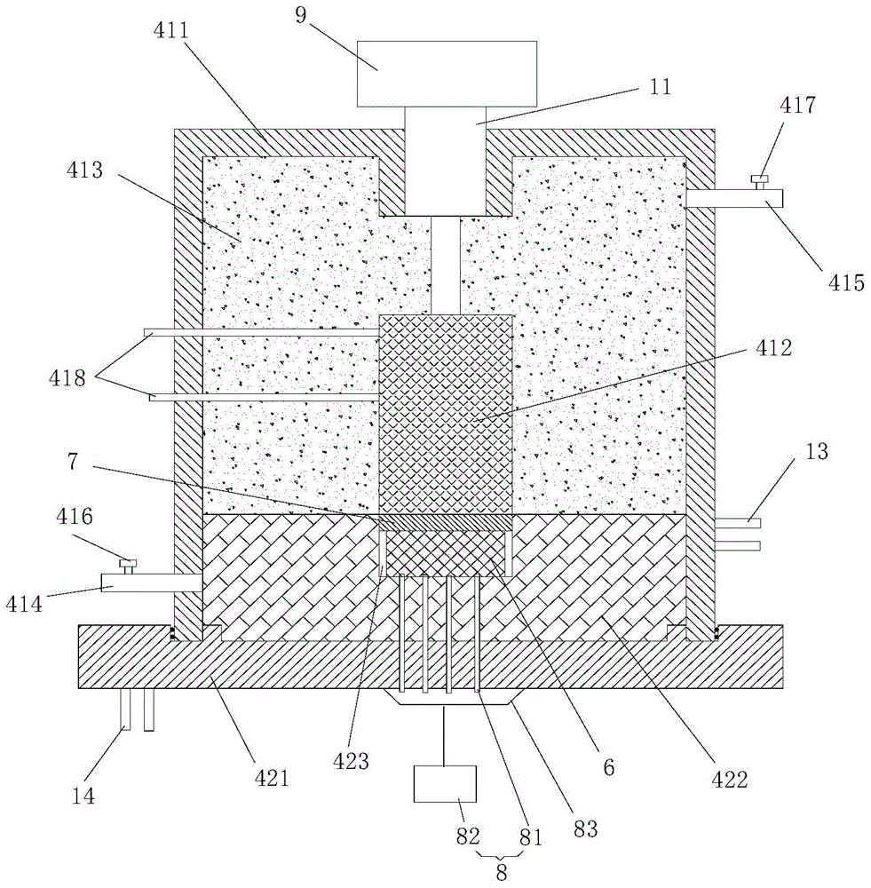
[0035] figure 1 It is a schematic structural diagram of the ultra-high temperature heat insulation performance test device of the embodiment of the present invention; figure 2 It is a structural schematic diagram of a heating furnace according to an embodiment of the present invention. figure 1 The dotted line indicates the electrical connection such as figure 1 and figure 2 As shown, the ultra-high temperature heat insulation performance tes...


PUM


Abstract

The invention discloses an ultra-high temperature heat-insulating property testing device and method. The ultra-high temperature heat-insulating property testing device comprises a heating furnace, wherein the heating furnace comprises a lower furnace body and an upper furnace body; the lower furnace body comprises a base and a base heat insulation layer arranged on the base; the top of the base heat insulation layer is downwards recessed to form a sample containing chamber; the upper furnace body comprises a furnace shell, an electric heating body arranged in the furnace shell, and a furnace shell heat insulation layer arranged between the electric heating body and the furnace shell; an air inlet and an air outlet communicated with the interior and exterior are formed in the furnace shell; valves are respectively arranged on the air inlet and the air outlet; after the upper furnace body is combined with the lower furnace body, the furnace shell and the base are combined to form a closed furnace chamber; the electric heating body is contacted with a heat-conducting gasket arranged on the top surface of the sample; contact-type heat conduction is realized between the electric heating body and the sample by virtue of the heat-conducting gasket; and the furnace shell heat insulation layer and the base heat insulation layer are contacted to form an overall heat insulation layer on the outer sides of the sample and the electric heating body. According to the device and method disclosed by the invention, the ultra-high temperature actual operation conditions can be simulated in a closed environment to the greatest degree.

Description

technical field [0001] The invention relates to the technical field of thermal insulation performance testing, in particular to an ultra-high temperature thermal insulation performance testing device and testing method. Background technique [0002] At present, the test devices for the high-temperature heat insulation performance of heat insulation materials can be divided into the following categories. One is a flat plate heat insulation performance measurement device that uses heating elements to be electrically heated, mainly using silicon carbide or molybdenum disilicide heating elements, and the maximum temperature does not exceed 1600℃, the simulated temperature is low, and the ultra-high temperature heat insulation performance test cannot be carried out; the second type of heat insulation performance test device is the radiation heat insulation test device, in which the radiation light source is mainly a quartz lamp, and the light source of a small number of devices is...

Claims


Application Information

Patent Timeline
Patent Type & Authority Applications(China)
IPC IPC(8): G01N25/20
Inventor 孙浩然陈玉峰陈曙光张世超王广海孙现凯邓可为李世新张峰方凯
Owner CHINA BUILDING MATERIALS ACAD
Learn More