Dynamic error testing method and device for intelligent ammeter

A smart energy meter, dynamic error technology, applied in measuring devices, measuring electrical variables, instruments, etc., can solve problems such as errors

Active Publication Date: 2015-04-29
BEIJING UNIV OF CHEM TECH
View PDF4 Cites 12 Cited by
  • Summary
  • Abstract
  • Description
  • Claims
  • Application Information

AI Technical Summary

Problems solved by technology

[0003] The purpose of the present invention is to solve the problem of comprehensive testing of the dynamic error characteristics of intelligent electric energy meters, electronic electric energy meters and inductive electric energy meters, to solve the method of generating pseudo-ra

Method used


Image

  • Dynamic error testing method and device for intelligent ammeter
  • Dynamic error testing method and device for intelligent ammeter
  • Dynamic error testing method and device for intelligent ammeter

Examples


specific Embodiment approach 1

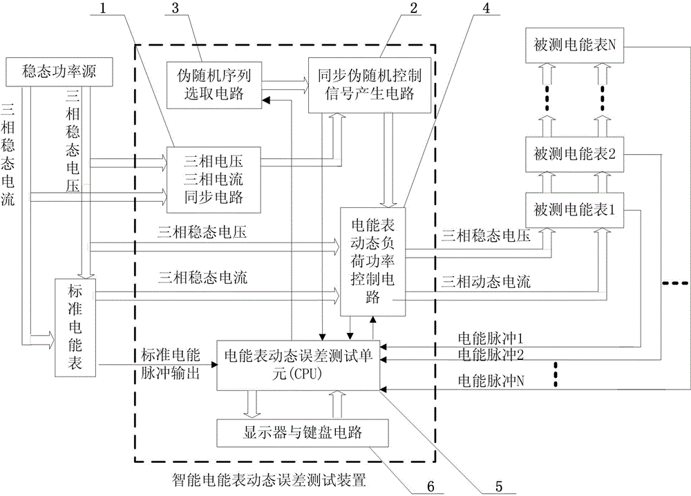
[0033] Specific implementation mode one: the following combination figure 1 This embodiment will be described. The method and device for testing the dynamic error of the smart electric energy meter described in this embodiment, which uses a synchronous circuit (1) of three-phase voltage and / or three-phase current to generate a synchronous pulse; the synchronous pulse is input into a synchronous pseudo-random sequence control signal generation circuit (2) , under the control of the pseudo-random sequence selection circuit (3), select a pseudo-random sequence output from a variety of pseudo-random sequences, and output the pseudo-random sequence to the dynamic load power control circuit (4) of the electric energy meter to generate pseudo-random changes Multi-mode dynamic load current and dynamic load power output, and generate steady-state voltage output. The input of the dynamic load power control circuit (4) of the electric energy meter is the steady-state voltage and steady-...

specific Embodiment approach 2

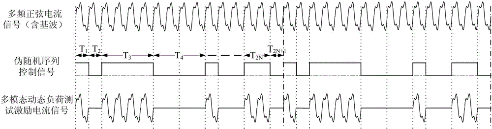
[0035] Specific implementation mode two: the following combination figure 1 Describe this embodiment, this embodiment is a further description of Embodiment 1, the synchronous pseudo-random sequence control signal s(t) described in this embodiment is:

[0036] s ( t ) = Σ k a ( k ) c ( t - kT )

[0037] In the formula, T is the period of the power frequency fundamental voltage or current; a(k) is a pseudo-random sequence with the value "1" or "0", k=0,1,2,3...belonging to the set N of natural numbers; c(t-kT) is the control signal level function:

[0038] V is the control level, the unit is volts.

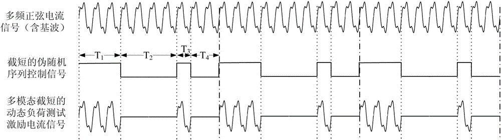
[0039] The pseudo-random sequence is an M sequence, an m sequence, a truncated m sequence, a balanced Gold sequence, a Gold seq...

specific Embodiment approach 3

[0045] Embodiment 3: This embodiment is a further description of Embodiment 1 and Method 2. The method of accumulating the output power of the test electric energy meter dynamic load power control circuit (4) in this embodiment is as follows: when the electric energy meter under test is When the dynamic load current and power are input, the energy meter dynamic error test unit (5) measures the cumulative time when the synchronous pseudo-random sequence control signal a(k) is "1" between the set N output pulses of the measured energy meter T Σ (1), while measuring a(k) is "0" the cumulative time is T Σ (0); T Σ ( 1 ) = T 1 + T 3 + · · · + T 2 N - 1 ...


PUM


Abstract

The invention relates to a dynamic error testing method and device for an intelligent ammeter. The device consists of a synchronous circuit with a three-phase voltage and/or a three-phase current, a synchronous pseudo random sequence control signal generating circuit, a pseudo random sequence selecting circuit, an ammeter dynamic load power control circuit, an ammeter dynamic error testing unit, a display and keyboard unit and a dynamic error measuring algorithm. The method and device can effectively generate multi-modal pseudo random testing excitation current and power and effectively reflect randomness of change of the dynamic load current and the power, thereby tracing the source from dynamic load electric energy value to a dynamic load electric energy value of the pseudo random change and fully testing the dynamic error characteristic of the ammeter under multi-modal testing excitation; the method and device solve the problem that exiting determined testing excitation current and power cannot reflect randomness of the dynamic load change and solve the problem of tracing the source of the dynamic load electric energy value and testing the dynamic error under dynamic load of the pseudo random change; the method and device can be widely used in a dynamic error testing system of the intelligent ammeter.

Description

technical field [0001] The present invention relates to a method and device for testing dynamic errors of smart electric energy meters, in particular to a method and device for testing dynamic errors of intelligent electric energy meters, electronic electric energy meters and inductive electric energy meters which can generate pseudo-random test excitation current and power. device. Background technique [0002] At present, dynamic loads in known smart grids are gradually increasing. On the one hand, distributed energy sources such as solar power, wind power, and biomass energy are introduced into the grid, making the power supply in the grid unstable. On the other hand, electrified railways, steel-making electric arc furnaces, rolling mills and large charging stations are widely used, and there are more and more dynamic loads in the power grid, resulting in a large increase in the measurement error of the electric energy meter under dynamic load. However, at present, the ...

Claims


Application Information

Patent Timeline
IPC IPC(8): G01R35/04
Inventor 王学伟王琳温丽丽贾晓璐
Owner BEIJING UNIV OF CHEM TECH
Why Eureka
Try Eureka