
High-temperature melt releasing device

A technology for releasing devices and melts, which can be used in emergency protection devices, greenhouse gas reduction, reactors, etc., and can solve problems such as ineffectiveness

Active Publication Date: 2015-04-29
SHANGHAI JIAO TONG UNIV
View PDF3 Cites 11 Cited by
  • Summary
  • Abstract
  • Description
  • Claims
  • Application Information

AI Technical Summary

Problems solved by technology

The ALPHA experimental device of Japan's JAERI has also successfully carried out a large number of interaction experiments between high-temperature melts and coolants, paying special attention to the rough mixing process. doesn't work

Method used


Image

  • High-temperature melt releasing device
  • High-temperature melt releasing device
  • High-temperature melt releasing device

Examples


Embodiment 1

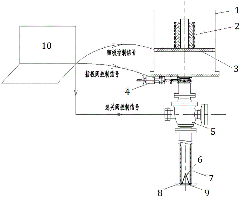
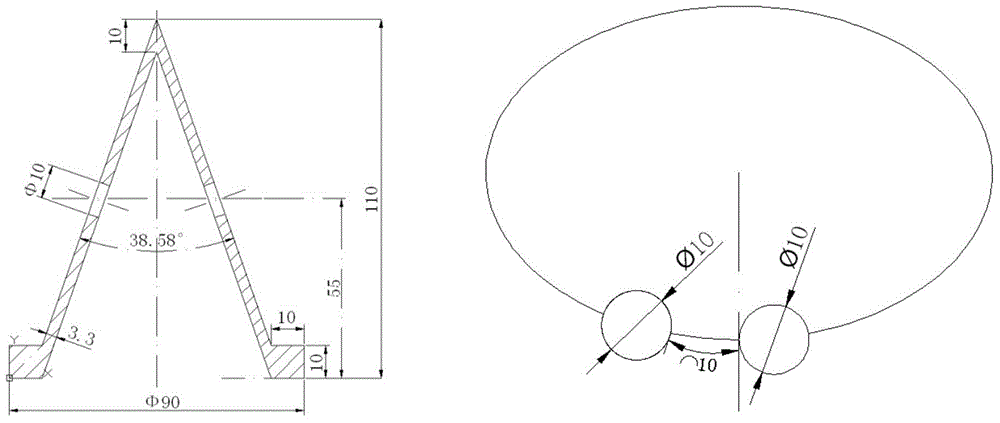
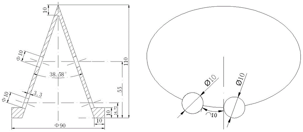
[0025] Such as figure 1 As shown, this embodiment includes: a pneumatic support mechanism and an impact mechanism arranged in sequence under the heating system 2 in the vacuum chamber 1, wherein the impact mechanism includes: a pipeline 7 connected to the pneumatic support mechanism and a pipeline 7 fixedly arranged inside the pipeline 7 The graphite cone 6, when the molten material passes through the graphite cone 6, the pneumatic support mechanism is completely closed in the time gap.

[0026] The pneumatic support mechanism includes: a pneumatic support flap 3 located under the melt heating device, and a flapper valve 4 and a quick-closing valve 5 which are airtightly connected to it in turn, wherein: the pneumatic support flap 3 and the flapper valve 4 and the quick-closing valve 5 are respectively connected with the console 10 and receive corresponding control signals.

[0027] The pneumatic support flap 3 is located at the bottom of the graphite crucible. Since the temp...


PUM


Abstract

The invention discloses a melt releasing device in the field of nuclear industry. The melt releasing device comprises a pneumatic support device and an impacting mechanism which are sequentially arranged under a melt heating device, wherein the impacting mechanism comprises a pipeline connected with the pneumatic support device, and a graphite cone fixedly arranged in the pipeline; the pneumatic support mechanism is completely closed within the time interval of a melt when passing through the graphite cone. The melt releasing device can be used for effectively releasing kilogram-grade high-temperature melt without influence on the normal use of other devices, so that a practical and feasible method is provided for experimental study of an interaction mechanism of the kilogram-grade high-temperature melt and a coolant; the technical support is provided for the development of large security analysis programs and the development of confirmatory experiments.

Description

technical field [0001] The invention relates to a technology in the field of the nuclear industry, in particular to a device for controlling the interaction between the high-temperature molten material and the coolant in a serious nuclear reactor accident to control the release of the kilogram-level high-temperature molten material. Background technique [0002] Energy has a particularly important strategic position in the national economy. I have seen that the current energy structure is unreasonable, primary energy consumption is dominated by coal, and the massive consumption of fossil energy has caused serious environmental pollution. In order to meet my country's continuously growing energy demand, the development of nuclear energy is the most effective and feasible. In the commercial and civilian use of nuclear energy, due to its own particularity, safety issues have always been the primary factor in the development of nuclear energy in my country, especially serious a...

Claims


Application Information

Patent Timeline
Patent Type & Authority Applications(China)
IPC IPC(8): G21C9/016
CPCG21C9/016Y02E30/30
Inventor 曹学武彭程佟立丽
Owner SHANGHAI JIAO TONG UNIV
Learn More